VOGONS


My Very Long Bus Adventure.

Topic actions

Reply 240 of 266, by Chadti99

User metadata
Rank Oldbie
Rank
Oldbie

Funny enough it works fine in the M919. Posted a 20.2 in Dosbench Quake at 180.

But it goes black on the m919 after post at 33Mhz fsb, which is probably just the M919 being it’s normal unpredictable self. Not sure if the VLB bus is divided like the PCI bus on this board.

Update 1: it worked the 2nd attempt at 33Mhz FSB 🤣. And there is a divisor on the VLB bus. Hit 20.7 after doing the FSB jumper trick to force 1:1 on pci.

Reply 241 of 266, by Chadti99

User metadata
Rank Oldbie
Rank
Oldbie

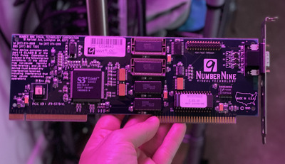
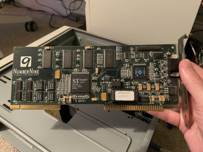
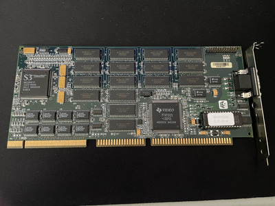
Recent VLB get, Number Nine Trio64, a 9FX Vision330 specifically. Lighting for dramatic effect. No interesting print on the back.

Attachments

Last edited by Chadti99 on 2022-09-06, 23:41. Edited 1 time in total.

Reply 242 of 266, by the3dfxdude

User metadata
Rank Member
Rank
Member
Chadti99 wrote on 2022-09-06, 23:11:

Recent VLB get, Number Nine Trio64. This is a GXE64 non-pro or a Vision330 maybe? Lighting for dramatic effect. No interesting print on the back.

I have this card. It's a vision 330. Says so on the floppy disks.

Same bios and essentially identical, except yours have the 2 ram sockets, and they skipped it on mine and soldered directly.

Reply 243 of 266, by Chadti99

User metadata
Rank Oldbie
Rank
Oldbie
the3dfxdude wrote on 2022-09-06, 23:41:
Chadti99 wrote on 2022-09-06, 23:11:

Recent VLB get, Number Nine Trio64. This is a GXE64 non-pro or a Vision330 maybe? Lighting for dramatic effect. No interesting print on the back.

I have this card. It's a vision 330. Says so on the floppy disks.

Same bios and essentially identical, except yours have the 2 ram sockets, and they skipped it on mine and soldered directly.

Nice! Thanks for confirming, there’s really no indication on the card itself. Initial tests prove it’s a decently quick board for dos gaming.

Reply 244 of 266, by Chadti99

User metadata
Rank Oldbie
Rank
Oldbie

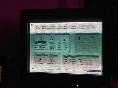
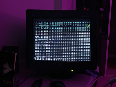
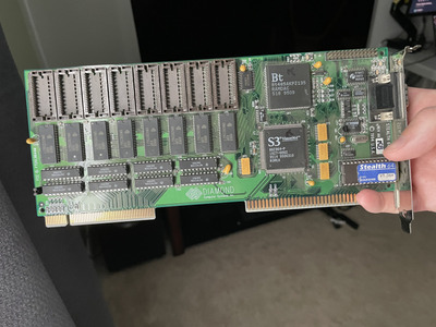
Recently acquired this Diamond Stealth 64 VLB card, based on the Vision 964, but unfortunately I’m seeing corrupted graphics. Any ideas, possible to repair? I’ve tried cleaning the contacts and tried it on a couple VLB motherboards.

Attachments

Reply 246 of 266, by GigAHerZ

User metadata
Rank Oldbie
Rank
Oldbie

Check for cold solder joints. Seems like 1-2 data bits are not coming through correctly. Maybe one or two pins on one of the memory chips are just not connected properly?

You may try to also press on each chip to see, if the problem goes away. But for that, in text mode, you probably want something that constantly rewrites the screen while you are massaging the card. 😉

"640K ought to be enough for anybody." - And i intend to get every last bit out of it even after loading every damn driver!

Reply 247 of 266, by Chadti99

User metadata
Rank Oldbie
Rank
Oldbie

Anyone heard of AGAtech or have any idea what these jumpers do?

Attachments

Reply 248 of 266, by Babasha

User metadata
Rank Oldbie
Rank
Oldbie
Chadti99 wrote on 2023-02-28, 11:04:

Anyone heard of AGAtech or have any idea what these jumpers do?

I think one jumper for VLB-BUS speed selection 25-33MHz or 40-50MHz and second for WAIT-STAIT selection 0WS or 1WS

Need help? Begin with photo and model of your hardware 😉

Reply 249 of 266, by GigAHerZ

User metadata
Rank Oldbie
Rank
Oldbie

Is the "Assign IRQ to VGA" also relevant to VLB graphics cards? That might also be one of the jumper's purpose.

"640K ought to be enough for anybody." - And i intend to get every last bit out of it even after loading every damn driver!

Reply 250 of 266, by Chadti99

User metadata
Rank Oldbie
Rank
Oldbie

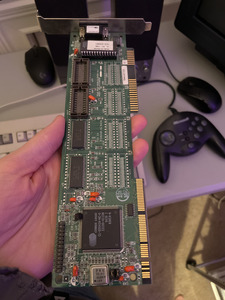
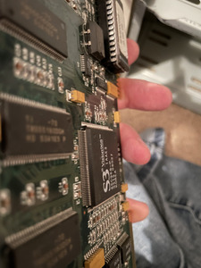
Been a minute since I’ve last updated, managed to snag a couple more interesting cards. This #9FX Motion 771 being one, unfortunately it is showing no signs of life. I’m not sure if this is the 2MB or 4MB version, another member here, Anonymous Coward, mentioned his 4MB version has chips on both sides, this one doesn’t. While attempting to diagnose I spotted a couple pins shorted to each other on the main 968 chip and fixed that, unfortunately did not catch that before powering on initially. I’ve tried flashing a bios I found on VGA museum but no luck. I’ve cleaned the contacts thoroughly with IPA and still just post beep errors for no video. If anyone has any further suggestions or know someone that could diagnose/repair let me know. I’ll upload the bios dump later today.

Attachments

  • IMG_2653.jpeg
    Filename
    IMG_2653.jpeg
    File size
    1.63 MiB
    Views
    921 views
    File license
    Fair use/fair dealing exception
  • IMG_2651.jpeg
    Filename
    IMG_2651.jpeg
    File size
    1.71 MiB
    Views
    921 views
    File license
    Fair use/fair dealing exception

Reply 252 of 266, by mkarcher

User metadata
Rank l33t
Rank
l33t
Chadti99 wrote on 2022-09-19, 19:39:

Recently acquired this Diamond Stealth 64 VLB card, based on the Vision 964, but unfortunately I’m seeing corrupted graphics. Any ideas, possible to repair? I’ve tried cleaning the contacts and tried it on a couple VLB motherboards.

GigAHerZ wrote on 2022-09-21, 13:59:

Check for cold solder joints. Seems like 1-2 data bits are not coming through correctly. Maybe one or two pins on one of the memory chips are just not connected properly?

I know the post is old, maybe my detailed troubleshooting tips are still appreciated:

If I read the screen dump correctly, the issue is clearly on the connection between PD0 (pin 100) of the Vision964 and the corresponding RAM chip pin. You might want to identify which chip is responsible for PD0. This can be quite easily done: The chip for the lowest eight data bits is connected to CAS0, which conveniently happens to be at a corner of the 964, making meter access easy. CAS0 is at pin 53, and it should connect to pin 27 of exactly one of the RAM chips. This RAM chip is supposed to be connected to PD0 to PD7, whcih are pins 91, 92 and 95 to 100. Pins 93 and 94 are power supply pins and need to be skipped when buzzing out stuff. These 8 data pins of the 964 are to be connected to pins 8-11 and 31-34 of the RAM chip you already identified by following CAS0. I don't expect there to be a straight mapping between "bit 0" of the 964 and "bit 0" of the RAM chip, because that would be unnecessary inconvenient to route on the PCB, but I given the symptoms, I expect you can find connections from PD1-PD7 to RAM pins, but you miss the PD0 connection. This might be a broken solder joint or a broken trace. After identifying which trace is the offending one, inspection and fixing should be straightforward.

Reply 253 of 266, by Anonymous Coward

User metadata
Rank l33t
Rank
l33t

The image of the Motion 771 is a little blurry, but it appears to have a VRM under the VGA port. Perhaps the memory chips are 3.3V? If possible, measure the voltage coming out of it.

"Will the highways on the internets become more few?" -Gee Dubya
V'Ger XT|Upgraded AT|Ultimate 386|Super VL/EISA 486|SMP VL/EISA Pentium

Reply 254 of 266, by mkarcher

User metadata
Rank l33t
Rank
l33t
Anonymous Coward wrote on 2023-10-16, 16:30:

The image of the Motion 771 is a little blurry, but it appears to have a VRM under the VGA port. Perhaps the memory chips are 3.3V? If possible, measure the voltage coming out of it.

It is a voltage regulator. The lettering "VR" on the silk screen is clearly visible.

On the other hand, VL is a 5V bus, the Vision 968 is a 5V chip with a 5V RAM interface, and the TMS55160 RAM is 5V, too. So everything except the DAC is clearly 5V and doesn't need a voltage regulator. It's likely that the voltage regulator is used as reference or power supply for the DAC. I found a image of a Motion 771 PCI, and could identify the Voltage Reculator as mic29150-3.3 (obviously a 3.3V regulator) and the DAC is an IBM RGB524. And indeed, the RGB524 is a 5V tolerant 3.3V chip.

Reply 255 of 266, by Chadti99

User metadata
Rank Oldbie
Rank
Oldbie
mkarcher wrote on 2023-10-15, 18:09:
I know the post is old, maybe my detailed troubleshooting tips are still appreciated: […]
Show full quote
Chadti99 wrote on 2022-09-19, 19:39:

Recently acquired this Diamond Stealth 64 VLB card, based on the Vision 964, but unfortunately I’m seeing corrupted graphics. Any ideas, possible to repair? I’ve tried cleaning the contacts and tried it on a couple VLB motherboards.

GigAHerZ wrote on 2022-09-21, 13:59:

Check for cold solder joints. Seems like 1-2 data bits are not coming through correctly. Maybe one or two pins on one of the memory chips are just not connected properly?

I know the post is old, maybe my detailed troubleshooting tips are still appreciated:

If I read the screen dump correctly, the issue is clearly on the connection between PD0 (pin 100) of the Vision964 and the corresponding RAM chip pin. You might want to identify which chip is responsible for PD0. This can be quite easily done: The chip for the lowest eight data bits is connected to CAS0, which conveniently happens to be at a corner of the 964, making meter access easy. CAS0 is at pin 53, and it should connect to pin 27 of exactly one of the RAM chips. This RAM chip is supposed to be connected to PD0 to PD7, whcih are pins 91, 92 and 95 to 100. Pins 93 and 94 are power supply pins and need to be skipped when buzzing out stuff. These 8 data pins of the 964 are to be connected to pins 8-11 and 31-34 of the RAM chip you already identified by following CAS0. I don't expect there to be a straight mapping between "bit 0" of the 964 and "bit 0" of the RAM chip, because that would be unnecessary inconvenient to route on the PCB, but I given the symptoms, I expect you can find connections from PD1-PD7 to RAM pins, but you miss the PD0 connection. This might be a broken solder joint or a broken trace. After identifying which trace is the offending one, inspection and fixing should be straightforward.

This is some really good info, and appreciate the detail. I should of updated the thread, I actually ended up returning the #9 964 card and found another that worked without issue. I'm tempted to return this 968 card given what I paid but you just don't see that many of these. I have hope!

Last edited by Chadti99 on 2023-10-16, 20:09. Edited 4 times in total.

Reply 256 of 266, by Chadti99

User metadata
Rank Oldbie
Rank
Oldbie
pshipkov wrote on 2023-10-15, 16:53:

I think i have seen this one on ebay recently.
Buy a cheap pci version and take the main IC from there.
Good chance it comes to live.

Not a bad idea, I'm tempted to try this.

Reply 257 of 266, by Chadti99

User metadata
Rank Oldbie
Rank
Oldbie
mkarcher wrote on 2023-10-16, 19:36:
Anonymous Coward wrote on 2023-10-16, 16:30:

The image of the Motion 771 is a little blurry, but it appears to have a VRM under the VGA port. Perhaps the memory chips are 3.3V? If possible, measure the voltage coming out of it.

It is a voltage regulator. The lettering "VR" on the silk screen is clearly visible.

On the other hand, VL is a 5V bus, the Vision 968 is a 5V chip with a 5V RAM interface, and the TMS55160 RAM is 5V, too. So everything except the DAC is clearly 5V and doesn't need a voltage regulator. It's likely that the voltage regulator is used as reference or power supply for the DAC. I found a image of a Motion 771 PCI, and could identify the Voltage Reculator as mic29150-3.3 (obviously a 3.3V regulator) and the DAC is an IBM RGB524. And indeed, the RGB524 is a 5V tolerant 3.3V chip.

That is interesting, I wonder why the VRM is needed. I can def put a meter on it.

Reply 258 of 266, by Chadti99

User metadata
Rank Oldbie
Rank
Oldbie

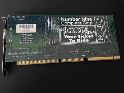
Here’s the other card I acquired. This one took a year from initial conversation with owner to arrive to me, I thought for sure I was being trolled or scammed with the length of time between updates on locating it and trying to find a way to ship. Fortunately this one works.

I believe this is quite obviously a #9 GXE 64 Pro. Will dump bios later.

Attachments

  • IMG_2678.jpeg
    Filename
    IMG_2678.jpeg
    File size
    1.92 MiB
    Views
    788 views
    File license
    Fair use/fair dealing exception
  • IMG_2677.jpeg
    Filename
    IMG_2677.jpeg
    File size
    1.66 MiB
    Views
    788 views
    File license
    Fair use/fair dealing exception
Last edited by Chadti99 on 2023-10-16, 20:31. Edited 2 times in total.

Reply 259 of 266, by mkarcher

User metadata
Rank l33t
Rank
l33t
Chadti99 wrote on 2023-10-16, 20:10:
mkarcher wrote on 2023-10-16, 19:36:

And indeed, the RGB524 is a 5V tolerant 3.3V chip.

That is interesting, I wonder why the VRM is needed. I can def put a meter on it.

If you still wonder why there is a VRM, I am sorry for using expert-only terms which were not clear enough. "a 5V tolerant 3.3V chip" means that this chip is a operating with 3.3V supply voltage. That's why the VRM (actually, it's not a voltage regulation module, just a voltage regulation chip) is needed. The IBM RGB524 will possibly blow up if you feed it with 5V. So why did call it 5V tolerant then, if it can not tolerate 5V supply? Because in electronics design language, this term is defined to mean "this chip can handle 5V on the data/signal lines even if it is powered by a lower voltage". The standard way of constructing chips designs input in a way that they are moderately resistant against ESD (electro-static discharge), but they can't withstand voltages above the supply voltage or below GND, because that case is treated like ESD. While small electro-static discharges have high voltage, they only have a tiny amount of power, so if the chip shorts that power out, the danger is gone. On the other hand, if you actively and continously supply voltages outside the permitted range, you might damage the chip.

"5V tolerant" means the chip is built in a special way that the ESD protection circuit is modified in a way that 5V on the data pins is not shorted to the 3.3V supply pin, so the chip works without any trouble when it receives 5V signals on some or all of its inputs (in case of the IBM DAC, all the signals it receives are 5V signals).