VOGONS


What retro activity did you get up to today?

Topic actions

Reply 31820 of 31841, by CharlieFoxtrot

User metadata
Rank Oldbie
Rank
Oldbie

Recapped Shuttle AB61 Spacewalker (440BX) and took a quick test that it boots and things seem fine in general. I found out from Shuttle archives that last BIOS update brought official Coppermine support for this board, something that theretroweb page for this board doesn't mention. So I had to naturally test it out with slotket and s370 700MHz Coppermine and sure enough, no problems. Overall it seems like a pretty neat little board.

The attachment 20260919_164454.jpg is no longer available

Reply 31821 of 31841, by smax

User metadata
Rank Newbie
Rank
Newbie

I tried to give my Dimension 4100 a speed boost in a couple different ways, to varying success.

Installed a USB 2.0 card and a 3.5" bay front panel USB header, everything went off without a hitch on that, and the speed boost will be super nice for transferring files. It's a StarTech VIA based 5 port card with internal header pins, so should be plenty for me.

Then I tried to install a Netgear GA311 gigabit network card. I'd had trouble installing it in 98SE a while back, I could never get the thing to work and gave up on it a while back. I've since installed XP on the machine so I figured I'd give it a go. Well, it still isn't recognized properly and would randomly hard lock my computer while I was trying to figure out the drivers for it. Sooo it's been yanked out again and will get trashed. Back to my trusty 3Com 3C905C 10/100 card I guess.

Dell Dimension 4100
Windows 98SE
733 MHz 1.0 GHz P3 Coppermine
512 MB PC133 RAM
ATI Radeon 9600XT
Sound Blaster Audigy SB0090

Reply 31822 of 31841, by Alesia

User metadata
Rank Newbie
Rank
Newbie

Well, I built out the socket 462 motherboard I got today (ASUS A7N266-VM) in a modern case just to make sure it worked, and it did with the Athlon XP 1800+ it came with. I tried to install the Athlon XP 2400+ I have since I thought it had the right bios version but it didn't post, so I took the risk and updated the bios from version 1004 to 1007, this was actually successful and it posted just fine with the 1800+ installed. I put the 2400+ back in and....no joy. I've bricked 1 motherboard via a bios update trying to get this CPU to go, and now a motherboard that for sure supports this CPU and actually has the right bios installed to support it can't post either? I'm starting to think the "working" Athlon XP 2400+ I was sold wasn't actually working. It's not a power supply issue, I have a known good power supply with 30A on the 5v rail, so it not even starting to post is a huge red flag at this point. One bummer after another lately :T

Reply 31823 of 31841, by RetroLizard

User metadata
Rank Member
Rank
Member
Alesia wrote on Yesterday, 04:58:

Well, I built out the socket 462 motherboard I got today (ASUS A7N266-VM) in a modern case just to make sure it worked, and it did with the Athlon XP 1800+ it came with. I tried to install the Athlon XP 2400+ I have since I thought it had the right bios version but it didn't post, so I took the risk and updated the bios from version 1004 to 1007, this was actually successful and it posted just fine with the 1800+ installed. I put the 2400+ back in and....no joy. I've bricked 1 motherboard via a bios update trying to get this CPU to go, and now a motherboard that for sure supports this CPU and actually has the right bios installed to support it can't post either? I'm starting to think the "working" Athlon XP 2400+ I was sold wasn't actually working. It's not a power supply issue, I have a known good power supply with 30A on the 5v rail, so it not even starting to post is a huge red flag at this point. One bummer after another lately :T

Do all the pins look fine? Does the board have a CPU plug for extra power?

Reply 31824 of 31841, by Alesia

User metadata
Rank Newbie
Rank
Newbie
RetroLizard wrote on Yesterday, 05:01:
Alesia wrote on Yesterday, 04:58:

Well, I built out the socket 462 motherboard I got today (ASUS A7N266-VM) in a modern case just to make sure it worked, and it did with the Athlon XP 1800+ it came with. I tried to install the Athlon XP 2400+ I have since I thought it had the right bios version but it didn't post, so I took the risk and updated the bios from version 1004 to 1007, this was actually successful and it posted just fine with the 1800+ installed. I put the 2400+ back in and....no joy. I've bricked 1 motherboard via a bios update trying to get this CPU to go, and now a motherboard that for sure supports this CPU and actually has the right bios installed to support it can't post either? I'm starting to think the "working" Athlon XP 2400+ I was sold wasn't actually working. It's not a power supply issue, I have a known good power supply with 30A on the 5v rail, so it not even starting to post is a huge red flag at this point. One bummer after another lately :T

Do all the pins look fine? Does the board have a CPU plug for extra power?

Pins all look perfect, as does the CPU die, no discoloration or anything that could indicate prior overheating. No extra CPU power connector , this generation didn't use those 100% of the time and the 2400+ is on the supported CPU list.

Edit: CPU Cooler isn't getting warm either, so the CPU isn't doing anything. (Gets immediately warm with the 1800+ installed)

Reply 31825 of 31841, by CharlieFoxtrot

User metadata
Rank Oldbie
Rank
Oldbie
Alesia wrote on Yesterday, 05:14:
RetroLizard wrote on Yesterday, 05:01:
Alesia wrote on Yesterday, 04:58:

Well, I built out the socket 462 motherboard I got today (ASUS A7N266-VM) in a modern case just to make sure it worked, and it did with the Athlon XP 1800+ it came with. I tried to install the Athlon XP 2400+ I have since I thought it had the right bios version but it didn't post, so I took the risk and updated the bios from version 1004 to 1007, this was actually successful and it posted just fine with the 1800+ installed. I put the 2400+ back in and....no joy. I've bricked 1 motherboard via a bios update trying to get this CPU to go, and now a motherboard that for sure supports this CPU and actually has the right bios installed to support it can't post either? I'm starting to think the "working" Athlon XP 2400+ I was sold wasn't actually working. It's not a power supply issue, I have a known good power supply with 30A on the 5v rail, so it not even starting to post is a huge red flag at this point. One bummer after another lately :T

Do all the pins look fine? Does the board have a CPU plug for extra power?

Pins all look perfect, as does the CPU die, no discoloration or anything that could indicate prior overheating. No extra CPU power connector , this generation didn't use those 100% of the time and the 2400+ is on the supported CPU list.

Edit: CPU Cooler isn't getting warm either, so the CPU isn't doing anything. (Gets immediately warm with the 1800+ installed)

Yeah, that CPU is dead as doornails if the heatsink isn't getting warm.

Gladly pretty much all these regular Thoroughbreds and Bartons are cheap and can be found easily, only Athlons that seem to have somewhat high asking prices are something like top of the line 3200+ and Athlon XP-ms. I have bunch of these and either fetched them for few euros or they came attached to some motherboard.

Reply 31826 of 31841, by Lopo

User metadata
Rank Newbie
Rank
Newbie

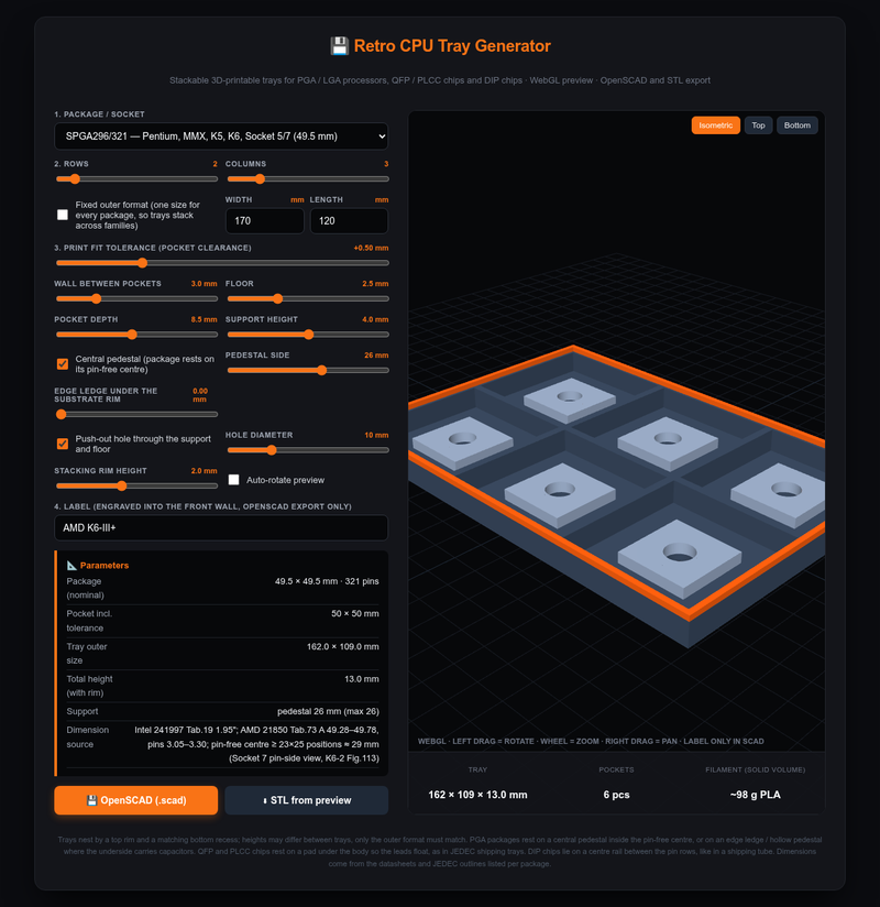
Today's retro activity was more CAD than retro: I got tired of CPUs rattling around in boxes, so I wrote a small generator for stackable 3D-printable chip trays.

Chip Tray Generator (runs in the browser, single HTML file, source on GitHub, MIT)

screenshot.png

What it does:

  • PGA/LGA CPUs from 386 (PGA132) through 486, Socket 5/7, 370, A, 423, 478, 754/939, AM2/AM3 up to LGA 775, plus QFP/PLCC and DIP chips in channels.
  • Pick a package, rows x columns, walls, tolerance; live 3D preview; export OpenSCAD (exact, parametric, engraved label) or STL.
  • Trays stack: rim on top, matching recess underneath. With "fixed outer format" trays for different sockets get the same footprint, so a 386 tray stacks on a Socket 7 tray.
  • The chip never rests on its pins: ceramic PGAs sit on a pedestal inside the pin-free centre, FC-PGA 370 on an edge ledge (Intel puts capacitors on the underside), QFP/PLCC on a pad under the body, DIPs on a centre rail like in a tube.

Package sizes and pin-free centres come from the datasheets (Intel 231630, 241997, 245264, AMD 25175, 21850, JEDEC outlines), not guesswork. What is NOT done yet: I haven't printed every variant, so if you print one and the tolerance or pedestal is off, tell me and I'll fix the defaults.

Reply 31827 of 31841, by Indrid_Cold_

User metadata
Rank Newbie
Rank
Newbie

Finally—and against all odds or hopes of successfully pulling it off again—I managed to migrate my old Miskatonic BBS (running on Mystic BBS software) from its last "exotic" hosting setup (a Huawei smartphone, PRoot, and Termux) to my barebone server, using an old, long-lost dump: Miskatonic BBS is BACK! (connect by fTelnet box: https://timrouter.dns.army/miskatonic/).

oLcUsdAvOQ
dKjMkCxaHA
jQm-leYqUg
UQwXrLz52A

Reply 31828 of 31841, by CharlieFoxtrot

User metadata
Rank Oldbie
Rank
Oldbie
Indrid_Cold_ wrote on Yesterday, 12:37:

Finally—and against all odds or hopes of successfully pulling it off again—I managed to migrate my old Miskatonic BBS (running on Mystic BBS software) from its last "exotic" hosting setup (a Huawei smartphone, PRoot, and Termux) to my barebone server, using an old, long-lost dump: Miskatonic BBS is BACK! (connect by fTelnet box: https://timrouter.dns.army/miskatonic/).

Nice, will check it at some point for sure. I hope it focuses 0n mystical Mythos studies and medieval metaphysics as the name implies!

Reply 31829 of 31841, by EduBat

User metadata
Rank Member
Rank
Member

Not today but this week...
For the past 5 years or so I had problems with my Seagate ST500DM002. There were always lots of DMA errors in the linux logs, Sata interface resets, etc. I always considered that this was normal, since the "average" hard drive failure rate is "100%" (they all fail eventually, eheheh) so I was not too bothered. All the important stuff was kept out of it anyway...
So, about 2 weeks it actually failed completely. Linux could no longer see the partition table and all of them were inaccessible.
This week, since I also wanted to install my "new" 5 1/4 inch floppy drive into the computer I decided to open it up and swap the drive.
This computer is based on a Gigabyte GA-7N400 Pro https://theretroweb.com/motherboards/s/gigabyte-ga-7n400-pro and the warning at the bottom of this retroweb page is spot on. At least 3 capacitors were found to be bulging and it was time to replace them.
All that done, all assembled and the SiI 3112 Sata controller was now unable to connect to any drives attached to it. Lots of tests with all sorts of cables and drives and nothing worked. All disassembled again and I noticed that I had accidentally broken a trace on the motherboard due to my poor eyesight and poor soldering skills. Fortunately I managed to take the board to a computer repair shop nearby and they fixed the trace.
Then, I tested it again and this it all worked, including the hard drive that gave me problems for years... Replacing that capacitor next to the SiI 3112 fixed all the issues I have had for half a decade... No more DMA errors, no more sata resets, all rock solid now.
Moral of the story, replace your dodgy capacitors!!!

Reply 31830 of 31841, by tehsiggi

User metadata
Rank Oldbie
Rank
Oldbie

I went a bit overboard this weekend with my current investigations into ATIs Rialto bridge.
While electrically everything is clear, there is the software component that has the most unknowns.

I know from schematics that the Rialto bridge is connected to the SPI EEPROM that is used by the GPU to store the BIOS. The question is: Why does the Rialto bridge need the EEPROM access and what's it doing with it?

My card to answer that is my X700 AGP and my X700 PCIe + a X700SE PCIe BIOS.


First I logged the complete SPI traffic using an RP2040 that is done by both the AGP and PCIe variant and found certain reads that the AGP card does before just loading the whole BIOS exactly like the PCIe one. This brought me forward to the point that I needed to test different BIOSes on the AGP card.

The goal: Take the X700SE PCIe BIOS (which also uses TSOP memory) and make it work on the AGP card with Rialto.


I built a test-jig with a Raspberry Pi Pico (RP2040), 74HC244 as a mux and moved the the EEPROM (SA25F005L) from the graphics card onto a SOP8 to DIP8 adapter.
This allows me to easily flash the EEPROM without need for software on the machine. This is especially important, since ATIflash will, dependent on the changes I do to the BIOS, not recognize the card anymore. The EEPROM needs to be isolated during programming from the card, because the Rialto bridge may assume the SPI master and then I'm locked out.

I flashed around 60 different BIOS permutations this way. It's very convenient. I tell the RP2040 to hand ownership of the EEPROM to itself (via the mux), then flash the BIOS via a small python program, then hand over ownership of the EEPROM to the graphics card. Next is just to restart the system under test and see if the BIOS works.

The attachment IMG_20260920_131844_preview.jpeg is no longer available
The attachment IMG_20260920_124906_preview.jpeg is no longer available
The attachment IMG_20260920_131848_preview.jpeg is no longer available

Since I know when the card is reading the BIOS contents from my SPI tracing, I know when it's safe to take over the EEPROM.

The attachment x700_weird_8.JPG is no longer available

Things I've seen so far:

  • Card not posting, board ignores GPU error and boots without it
  • Card not posting, stuck at boot code 25
  • Card not posting, stuck at boot code 26
  • Card posting, ATIflash not enumerating it
  • Card posting, but in Windows I have 8 (!!!) X700 devices listed, driver bluescreens
  • Card posting, but in Windows I have 8 X700 devices listed and one of them installs successfully + 3D works
  • Modified X700SE PCIe BIOS + block for Rialto booting and running 3D successfully

I'm not far enough to conclude everything, but this weekend has been awesome and I can't wait to write it all up.

And for the kicks: Here is Rialto under load without any airflow:

The attachment img_thermal_1789924167607_preview.jpeg is no longer available

AGP Card Real Power Consumption
AGP Power monitor - diagnostic hardware tool
Graphics card repair collection

Reply 31831 of 31841, by Dothan Burger

User metadata
Rank Member
Rank
Member
Lopo wrote on Yesterday, 08:31:
Today's retro activity was more CAD than retro: I got tired of CPUs rattling around in boxes, so I wrote a small generator for s […]
Show full quote

Today's retro activity was more CAD than retro: I got tired of CPUs rattling around in boxes, so I wrote a small generator for stackable 3D-printable chip trays.

Chip Tray Generator (runs in the browser, single HTML file, source on GitHub, MIT)

screenshot.png

What it does:

  • PGA/LGA CPUs from 386 (PGA132) through 486, Socket 5/7, 370, A, 423, 478, 754/939, AM2/AM3 up to LGA 775, plus QFP/PLCC and DIP chips in channels.
  • Pick a package, rows x columns, walls, tolerance; live 3D preview; export OpenSCAD (exact, parametric, engraved label) or STL.
  • Trays stack: rim on top, matching recess underneath. With "fixed outer format" trays for different sockets get the same footprint, so a 386 tray stacks on a Socket 7 tray.
  • The chip never rests on its pins: ceramic PGAs sit on a pedestal inside the pin-free centre, FC-PGA 370 on an edge ledge (Intel puts capacitors on the underside), QFP/PLCC on a pad under the body, DIPs on a centre rail like in a tube.

Package sizes and pin-free centres come from the datasheets (Intel 231630, 241997, 245264, AMD 25175, 21850, JEDEC outlines), not guesswork. What is NOT done yet: I haven't printed every variant, so if you print one and the tolerance or pedestal is off, tell me and I'll fix the defaults.

That's really cool, I'll try the 478 tray tonight on my old Ender 3.

Reply 31832 of 31841, by dormcat

User metadata
Rank Oldbie
Rank
Oldbie

Cleaned up the degraded thermal tape between the heatsink and the main chip of my no-brand Voodoo Banshee reference board.

The attachment Banshee.jpg is no longer available

Will need a new thermal pad or tape. Plus a new 4×4 cm fan.

Reply 31833 of 31841, by Indrid_Cold_

User metadata
Rank Newbie
Rank
Newbie
CharlieFoxtrot wrote on Yesterday, 13:04:
Indrid_Cold_ wrote on Yesterday, 12:37:

Finally—and against all odds or hopes of successfully pulling it off again—I managed to migrate my old Miskatonic BBS (running on Mystic BBS software) from its last "exotic" hosting setup (a Huawei smartphone, PRoot, and Termux) to my barebone server, using an old, long-lost dump: Miskatonic BBS is BACK! (connect by fTelnet box: https://timrouter.dns.army/miskatonic/).

Nice, will check it at some point for sure. I hope it focuses 0n mystical Mythos studies and medieval metaphysics as the name implies!

Thanks. You could say that was the original idea - or rather, a more "expansive" one: using this medium - an old-school one, certainly mature, and one that filters its users based on "technical" maturity - to talk about absolutely anything with total freedom - even the "forbidden" - thinking about and debating topics "far" from the mainstream line and the prevailing orthodoxy. Unfortunately, where I live, it’s becoming increasingly hard to find curious, capable people who still possess that "spark" for experimentation and sharing... the social media circus has taken over, yet there is still a solid little community behind BBSs, and some of them are truly spectacular.

oLcUsdAvOQ
dKjMkCxaHA
jQm-leYqUg
UQwXrLz52A

Reply 31834 of 31841, by Alesia

User metadata
Rank Newbie
Rank
Newbie
CharlieFoxtrot wrote on Yesterday, 08:00:
Alesia wrote on Yesterday, 05:14:
RetroLizard wrote on Yesterday, 05:01:

Do all the pins look fine? Does the board have a CPU plug for extra power?

Pins all look perfect, as does the CPU die, no discoloration or anything that could indicate prior overheating. No extra CPU power connector , this generation didn't use those 100% of the time and the 2400+ is on the supported CPU list.

Edit: CPU Cooler isn't getting warm either, so the CPU isn't doing anything. (Gets immediately warm with the 1800+ installed)

Yeah, that CPU is dead as doornails if the heatsink isn't getting warm.

Gladly pretty much all these regular Thoroughbreds and Bartons are cheap and can be found easily, only Athlons that seem to have somewhat high asking prices are something like top of the line 3200+ and Athlon XP-ms. I have bunch of these and either fetched them for few euros or they came attached to some motherboard.

There's not really that much on ebay and they run $35-80 USD. Wish I could say I was able to pick up a bunch of free systems to harvest parts from, but that era of stuff has rapidly dried up in my area.

Edit: Might as well put my daily activities here while I'm at it. Got XP SP3 installed on this Socket 462 PC and started moving over GOG installers so that the long transfer times are over with by the time my HD 3650 arrives and I get down to installing drivers. I was a bit suprised this board has USB 2.0 support...or rather mass storage USB support but it's nice that it does. The manual/specs make no mention of the USB type s I wasn't sure. Also archiving two driver floppies, one from the NOS keyboard I bought for this, and another from a floppy drive I got that had this random CD driver floppy included.

Reply 31835 of 31841, by StriderTR

User metadata
Rank Oldbie
Rank
Oldbie

Got my PicoPEB sidecar device built this weekend and tested. So far, it's working good. I just need to pick up a SM 100uf cap and a couple 1/4 watt resistors to replace ones I used on-hand to get it up and running.

32K RAM expansion, 8MB SAMS, GROM and disk emulation, speech synthesizer emulation, and more. This is a fun project!

Once I had the proper replacement parts, then I can print it a nice case and move on to the Pico9918 and Atari joystick adapter!

DOS, Win9x, General "Retro" Enthusiast. Professional Tinkerer. Technology Hobbyist. Expert at Nothing! Build, Create, Repair, Repeat!
This Old Man's Builds, Projects, and Other Retro Goodness: https://theclassicgeek.blogspot.com/

Reply 31836 of 31841, by Dothan Burger

User metadata
Rank Member
Rank
Member
tehsiggi wrote on Yesterday, 18:41:

The goal: Take the X700SE PCIe BIOS (which also uses TSOP memory) and make it work on the AGP card with Rialto.

This project looks incredible, though I admit I don't fully understand the end goal. Still I can't wait to learn more about the rialto.

Reply 31837 of 31841, by tehsiggi

User metadata
Rank Oldbie
Rank
Oldbie
Dothan Burger wrote on Yesterday, 23:58:
tehsiggi wrote on Yesterday, 18:41:

The goal: Take the X700SE PCIe BIOS (which also uses TSOP memory) and make it work on the AGP card with Rialto.

This project looks incredible, though I admit I don't fully understand the end goal. Still I can't wait to learn more about the rialto.

If we learn how the bridge works, we might be able to adapt it to not yet released cards. And I'd like to come to a point where in can determine if the GPU is bad or the bridge.

AGP Card Real Power Consumption
AGP Power monitor - diagnostic hardware tool
Graphics card repair collection

Reply 31838 of 31841, by Lopo

User metadata
Rank Newbie
Rank
Newbie
Dothan Burger wrote on Yesterday, 19:07:
Lopo wrote on Yesterday, 08:31:
Today's retro activity was more CAD than retro: I got tired of CPUs rattling around in boxes, so I wrote a small generator for s […]
Show full quote

Today's retro activity was more CAD than retro: I got tired of CPUs rattling around in boxes, so I wrote a small generator for stackable 3D-printable chip trays.

Chip Tray Generator (runs in the browser, single HTML file, source on GitHub, MIT)

screenshot.png

What it does:

  • PGA/LGA CPUs from 386 (PGA132) through 486, Socket 5/7, 370, A, 423, 478, 754/939, AM2/AM3 up to LGA 775, plus QFP/PLCC and DIP chips in channels.
  • Pick a package, rows x columns, walls, tolerance; live 3D preview; export OpenSCAD (exact, parametric, engraved label) or STL.
  • Trays stack: rim on top, matching recess underneath. With "fixed outer format" trays for different sockets get the same footprint, so a 386 tray stacks on a Socket 7 tray.
  • The chip never rests on its pins: ceramic PGAs sit on a pedestal inside the pin-free centre, FC-PGA 370 on an edge ledge (Intel puts capacitors on the underside), QFP/PLCC on a pad under the body, DIPs on a centre rail like in a tube.

Package sizes and pin-free centres come from the datasheets (Intel 231630, 241997, 245264, AMD 25175, 21850, JEDEC outlines), not guesswork. What is NOT done yet: I haven't printed every variant, so if you print one and the tolerance or pedestal is off, tell me and I'll fix the defaults.

That's really cool, I'll try the 478 tray tonight on my old Ender 3.

Thanks! The 478 tray is a good test case: that package has capacitors on the underside, so the CPU doesn't sit on a centre pedestal but on a 1.25 mm ledge around the pocket edge (the substrate rim outside the pin field is only ~1.6 mm). If you can, three things would help me fix the defaults:

  • the printed pocket width with calipers (nominal is 35.5 mm with the default +0.5 mm tolerance),
  • whether the CPU rests on the ledge with the pins clear of the floor (a sheet of paper under the pins should slide freely),
  • if you print two, whether the rim of one nests into the recess of the other.

The OpenSCAD export is the exact one; the STL from the preview is fine for a test print too.

Reply 31839 of 31841, by H3nrik V!

User metadata
Rank l33t
Rank
l33t
Lopo wrote on Yesterday, 08:31:
Today's retro activity was more CAD than retro: I got tired of CPUs rattling around in boxes, so I wrote a small generator for s […]
Show full quote

Today's retro activity was more CAD than retro: I got tired of CPUs rattling around in boxes, so I wrote a small generator for stackable 3D-printable chip trays.

Chip Tray Generator (runs in the browser, single HTML file, source on GitHub, MIT)

screenshot.png

What it does:

  • PGA/LGA CPUs from 386 (PGA132) through 486, Socket 5/7, 370, A, 423, 478, 754/939, AM2/AM3 up to LGA 775, plus QFP/PLCC and DIP chips in channels.
  • Pick a package, rows x columns, walls, tolerance; live 3D preview; export OpenSCAD (exact, parametric, engraved label) or STL.
  • Trays stack: rim on top, matching recess underneath. With "fixed outer format" trays for different sockets get the same footprint, so a 386 tray stacks on a Socket 7 tray.
  • The chip never rests on its pins: ceramic PGAs sit on a pedestal inside the pin-free centre, FC-PGA 370 on an edge ledge (Intel puts capacitors on the underside), QFP/PLCC on a pad under the body, DIPs on a centre rail like in a tube.

Package sizes and pin-free centres come from the datasheets (Intel 231630, 241997, 245264, AMD 25175, 21850, JEDEC outlines), not guesswork. What is NOT done yet: I haven't printed every variant, so if you print one and the tolerance or pedestal is off, tell me and I'll fix the defaults.

Briliant tool! Had it been there before I designed my own, I'd definetely use that.

I found a little glitch though

Using 178x130 milimeters as outer limits (to fit the trays I've designed myself), selecting DIP-20 and above the pockets gets outside of the tray.

If it's dual it's kind of cool ... 😎

--- GA586DX --- P2B-DS --- BP6 ---

Please use the "quote" option if asking questions to what I write - it will really up the chances of me noticing 😀