Reply 20 of 42, by maxtherabbit
Rank
l33t
- Rank
- l33t
if a tantalum explodes when you power it on just replace it and carry on, it's not going to destroy anything else
if a tantalum explodes when you power it on just replace it and carry on, it's not going to destroy anything else
You're right. I'm acting overly cautious. However, i'm going to make sure to document each component, before I'll do the smoke test.
I'm definetely going to wear safety googles, that's for sure.
Oh well, here goes nothing.
If nothing gets in my way, i'm going to test my board today, in hope that the no components release the magic smoke.
But I did some further measurements and found following.
All the +5v pins are providing continuity to each other, I think think that's normal behavior.
Also all the ground pins are providing continuity, i'm certain, this is supposed to be like that.
I came to the conclusion, that none of the other pins provide conitnuity, therefore i'm fairly certain, that none of the suspected components are shorted.
I'm gonna risk it and see what happens, when I test it with a known-good power supply.
Wilius wrote on 2021-08-11, 07:13:If nothing gets in my way, i'm going to test my board today, in hope that the no components release the magic smoke. But I did s […]
If nothing gets in my way, i'm going to test my board today, in hope that the no components release the magic smoke.
But I did some further measurements and found following.
All the +5v pins are providing continuity to each other, I think think that's normal behavior.
Also all the ground pins are providing continuity, i'm certain, this is supposed to be like that.
I came to the conclusion, that none of the other pins provide conitnuity, therefore i'm fairly certain, that none of the suspected components are shorted.
I'm gonna risk it and see what happens, when I test it with a known-good power supply.
Yes, it's completely normal that the +5V and GND pins are connected to common +5V and GND rails respectively. They transport quite large currents. Using more than one connection/wire for a given voltage, you can get away with using smaller/simpler connectors, and thinner wire gauges. As for other voltages and signals, the currents are much smaller, one connection/wire each is enough.
BitWrangler wrote on 2021-08-10, 16:48:Yeah, that was the joke...they took one down with a long cable... from the 2nd Star Wars movie, Episode 5, Empire Strikes Back, which is now the 7th in Chronological sequence or 8th if you include Clone Wars animated, possibly the 19th or so by the time they're done turning that horse to mulch, and I ain't got a clue where Mandalorian fits.
Just like there are only 2 Alien movies and 2 Terminator movies, there are only 3 Star Wars movies.
Is this too much voodoo?
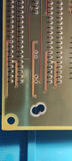
Good thing I haven't done the smoketest yet, because I just found a shorted tantalum capacitor between the bottom 8-bit and 16-bit ISA slots.
Or so I thought.
Even after removing the suspected capacitor, the short is still there. And worst of all, I don't know where the traces are leading.
I have no clue what component could be causing the short.
I am starting to become desperate. I don't know how to proceed at this point. Any ideas, what could cause the short and what I should do now?
If you need specific pictures of the board, please tell me.
there will be multiple tantalums on the same voltage rail, you can either
1) use a fairly precise DMM on each shorted one to see which has the absolute lowest resistance
2) turn it on and replace whichever one blows up 🤣
maxtherabbit
I have my suspicions, that none of the tantalums are causing the short, as I already checked every single tantalum on this board.
But I guess, I have no other choice but to turn it on and see what blows up.
Gosh, this feels so wrong.
I hope none of the active components releases the magic smoke.
Should I perhaps remove every socketed IC, before I turn on the board?
edit: When I'm using a multimeter and hold one tip against the ground pin of the AT-connector and the other against the solderpads/contacts where the tantalum capacitor used to be (currently removed), I have continuity on both contacts.
This can't be normal, right?
which power rail is shorted? check it at the connector where you would ordinarily connect the PSU to see which pin is shorted to ground
This board is driving me nuts, there's 100% no short between the power rails themselves, but then there is a short between the spot where the capacitor was.
I'm too stupid to understand what's going on. I just don't get it.
Screw it, i'm gonna turn this board on, regardless of the shorted area. Maybe the aftermaths won't be that bad.
I've wasted your time for way too long.
On a sidenote: My DMM is not precise enough to measure the resistance of the capacitors. I'll have to get better Measurement tools.
I have great news.
My board passed the smoketest.
There's even a beep code.
It does 1x long beep and 8x short beeps.
I think it means there is a video error, which makes sense, because I've tested it without a graphics card.
Or am I mistaken?
For some reason my POST-card didn't work though.
I'm looking into getting a VGA card soon to do some further testings.
So far everything is looking great for me.
Should I solder the capacitor, which I removed, back into the board to see what's gonna happen?
Here is a short video of the beep code: https://youtu.be/v793RK3-xcY
That's correct, it is the no video beep code.
Yeah put the cap back but make certain it's in the same orientation as it came out. They are polarized
Thanks for the friendly reminder.
I've accidentally damaged the original capacitor when I desoldered it from the board.
Thankfully, I already found a fitting replacement.
But, i'm uncertain, which of the legs is the + side on the replacement capacitor.
I believe, the leg where the long stripe is, is the + side.
Take a look. The one on the left is the replacement capacitor.
I'm sorry for the broken english.
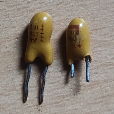
the "stripe" is 6 '+' symbols, that is the positive leg
I've soldered the capacitor back on and everything seems to work just fine.
With that being said, I think all issues of the board are resolved.
Next up, I'm going to get a VGA card to see, if there's going to be anything displayed on the screen.
As soon as I have a card, I'll update you. Till then I'll put this thread on hold.
Thanks for your amazing help so far, without you guys I wouldn't have come this far.
Forget what I said earlier, I won't put my thread on hold yet.
I have more questions, before I focus on the power supply, which is gonna take some time.
I have a 5.25" Seagate ST-251 hard drive, a 5.25" CHINON FZ-506 floppy disk drive and a Western Digital WD1006V-SR2 controller card.
I've never worked with 5.25" MFM drives before, therefore I have no idea how to connect them.
Can someone please tell me in which direction goes the Control Connector of both the FDD and HDD, and in which direction goes the Data Connector of the HDD?
I need the pin layout of the ST-251 hard drive or any MFM hard drive for this matter, which shows where pin 1 and pin 34 are on the Control connector and where pin 1 and pin 20 are on the data connector.
The same goes for my Western Digital controller card.
All my cables have red stripes on the very edge. In which direction are they supposed to be facing?
On the HDD control cable, the red stripe is right beneath pin # 33, while on the FDD cable it's right beneath pin # 1. On the data cable the red strip is beneath pin # 19.
There are also plastic spacers which are going into the notch of the edge connectors from the hard drive. However, someone had already removed them before me, therefore I don't know anymore in which direction they were supposed to be facing.
Except for the plastic spacers, all questions from above also apply to my floppy disk drive and its dedicated connector on my controller card.
I'm sorry for asking so many questions, it's only the second time I'm working on hardware this old and I still need to learn a lot.
I also apologize in case this sounds like utter gibberish - if you didn't understood something, please let me know.
Thanks in advance.
P.S. Let me know if you need any specific pictures.
The cable stripe should always goes to pin 1 on all HD and floppy and controller. On the controller pin 1 should be labeled (as my WD1006v-sr2 late model has 1 & 2 on one side of row of pins). You need 20pin DATA cable on Drive 0.
On your Seagate ST-251 there should be a "notch" in the edge connectors so if using original MFM/RLL cables it should plug in only one way on the drive, if using after market: the pin 1 side are closest to the Power connector.
see this picture and follow the cable from pin 1 on controller to the Seagate HD do same:
https://i0.wp.com/avitech.com.au/wp-content/u … ler-cropped.jpg
For floppy same thing, stripe on pin 1. The cable end to floppy slot connection should be notched and should only fit one way. It appears on your Chinon FZ-506 pin 1 is opposite side from the power connector.
Hopefully some one else will also verify this before you try it.
Hate posting a reply and then have to edit it because it made no sense 😁 First computer was an IBM 3270 workstation with CGA monitor. Stuff: https://archive.org/details/@horun
This looks and sounds promising, does it?
What do you think, is my machine behaving normally?
I can't hook it up to a display in the moment, because the original power supply is still faulty and I don't have a VGA card yet.
https://youtu.be/OYMjrk-jEU8
appears to be working normally, sans video


