VOGONS


Reply 320 of 1197, by Sphere478

User metadata
Rank l33t++
Rank
l33t++

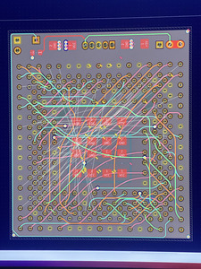
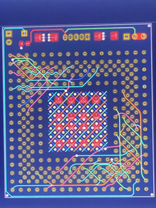
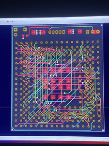
Yeah, I know. It’s a mess still. Not even beta yet man 😀 it’ll get there. Thanks for the feedback though. It is important.

Not much point in pointing out flaws just yet as there are so many left to fix. Gimme a little bit to attack the trace and plane routing and then get back to me 😀 ground islands and right angle traces are definitely on my radar. 😀 if I can’t land both ends of that plane somehow by playing with the traces I’ll probably add a via to the ends to kill the antenna effect as you call it.

I saw that effect first hand on microwaves. It was wild how a bad spot weld in a waveguide connected elsewhere would still get a induced voltage difference and spark right in the middle of all that metal.

Sphere's PCB projects.
-
Sphere’s socket 5/7 cpu collection.
-
SUCCESSFUL K6-2+ to K6-3+ Full Cache Enable Mod
-
Tyan S1564S to S1564D single to dual processor conversion (also s1563 and s1562)

Reply 321 of 1197, by Sphere478

User metadata
Rank l33t++
Rank
l33t++

I've done some pondering and am going to start over on the trace routing entirely. It has been in the back of my mind that clocking the socket differently may give better routing possibilities. Also having pin 1 on two different corners is really bugging me

I left the large socket as is and am going to try a slightly modified method of trace routing that focuses on minimizing vias. and not being so stringent on the direction traces are going on each layer.

and as a bonus surprise, bendy traces.

Attachments

  • image.jpg
    Filename
    image.jpg
    File size
    1.81 MiB
    Views
    854 views
    File license
    Public domain

Sphere's PCB projects.
-
Sphere’s socket 5/7 cpu collection.
-
SUCCESSFUL K6-2+ to K6-3+ Full Cache Enable Mod
-
Tyan S1564S to S1564D single to dual processor conversion (also s1563 and s1562)

Reply 323 of 1197, by Sphere478

User metadata
Rank l33t++
Rank
l33t++

Thx 😀

Calamitylime found a plug in somewhere that tear dropps the ends also, I could try looking into that.

I’m having trouble getting some routed. I think this has a lot to do with trying to use larger traces.

I’ve started using the top and bottom layers also to try and keep the larger traces 🙁

Sphere's PCB projects.
-
Sphere’s socket 5/7 cpu collection.
-
SUCCESSFUL K6-2+ to K6-3+ Full Cache Enable Mod
-
Tyan S1564S to S1564D single to dual processor conversion (also s1563 and s1562)

Reply 324 of 1197, by Sphere478

User metadata
Rank l33t++
Rank
l33t++

This is quite the puzzle.

Trying a bunch of different ideas. One of these ideas is bound to be better than the rest. 😀

Thoughts H3nrik V!? Both approaches aren’t finished but what do you think has better attributes? This way or previous way?

I can probably spread out those signals in the middle a bit, maybe even stagger them layer to layer. 🤔

Attachments

  • image.jpg
    Filename
    image.jpg
    File size
    1.57 MiB
    Views
    810 views
    File license
    Public domain

Sphere's PCB projects.
-
Sphere’s socket 5/7 cpu collection.
-
SUCCESSFUL K6-2+ to K6-3+ Full Cache Enable Mod
-
Tyan S1564S to S1564D single to dual processor conversion (also s1563 and s1562)

Reply 325 of 1197, by H3nrik V!

User metadata
Rank Oldbie
Rank
Oldbie

Well, I'm not a fan of those soft curves on the tracks - probably mostly for an ocd point of view 🤣 otoh I've never been a fan of the "x-layer, y-layer" philosophy, all though that is a proven widely used way of routing. I probably more "feel" how I want it to be, but preferably always trying to get room between tracks for connected ground in both ends ... But then again, my pcbs have been laid out to meet all sorts of emc/emi requirements, which is not a hard requirement on hobby pcbs, all though it can prevent all sorts of other problems ...
Damnit, I'm avoiding a direct answer here .. Mostly probably because both ways will work fine and at the end of the day being a question of ease of routing and aesthetics. Only thing is - never ever ignore having a full ground as well as a supply plane, preferably with the same z-spacing to routing layers.

Please use the "quote" option if asking questions to what I write - it will really up the chances of me noticing 😀

Reply 326 of 1197, by Sphere478

User metadata
Rank l33t++
Rank
l33t++

Got another idea on the drawing board.

Since with this clocking of the socket there is a lot of tracks going lower left to upper right I am trying to run a bunch of evenly spaced tracks with ground planes stitched between. And will use the lower layer (blue) for lower right to upper left.

Attachments

  • image.jpg
    Filename
    image.jpg
    File size
    1.7 MiB
    Views
    761 views
    File license
    Public domain

Sphere's PCB projects.
-
Sphere’s socket 5/7 cpu collection.
-
SUCCESSFUL K6-2+ to K6-3+ Full Cache Enable Mod
-
Tyan S1564S to S1564D single to dual processor conversion (also s1563 and s1562)

Reply 327 of 1197, by H3nrik V!

User metadata
Rank Oldbie
Rank
Oldbie

I don't have the full overview, but would there be a benefit from rotating one of the sockets in terms of routing it all?

Please use the "quote" option if asking questions to what I write - it will really up the chances of me noticing 😀

Reply 328 of 1197, by Sphere478

User metadata
Rank l33t++
Rank
l33t++
H3nrik V! wrote on 2022-09-22, 03:52:

I don't have the full overview, but would there be a benefit from rotating one of the sockets in terms of routing it all?

Some orientations are better than others but not by much. Its almost like they flipped the die inside the package and made this mess.

I’m trying to make this orientation work currently because it puts pin 1 in the same corner on both sockets. I figured that would be best.

Sphere's PCB projects.
-
Sphere’s socket 5/7 cpu collection.
-
SUCCESSFUL K6-2+ to K6-3+ Full Cache Enable Mod
-
Tyan S1564S to S1564D single to dual processor conversion (also s1563 and s1562)

Reply 329 of 1197, by feipoa

User metadata
Rank l33t++
Rank
l33t++

Yeah, having pin 1 in the same corner for both PGA132 and PGA168 would reduce the probability of the unit being inserted incorrectly. However, if there's a much more ideal rotation for routing traces, I think that would take priority.

Plan your life wisely, you'll be dead before you know it.

Reply 330 of 1197, by Sphere478

User metadata
Rank l33t++
Rank
l33t++

All the orientations suck to be honest. We may as well choose pin 1

Sphere's PCB projects.
-
Sphere’s socket 5/7 cpu collection.
-
SUCCESSFUL K6-2+ to K6-3+ Full Cache Enable Mod
-
Tyan S1564S to S1564D single to dual processor conversion (also s1563 and s1562)

Reply 331 of 1197, by Sphere478

User metadata
Rank l33t++
Rank
l33t++

May have had that clever idea I was looking for.

The blue traces are only on the blue outer layer.

But The other rows going the other way utilize all four inner layers but there are only two traces stacked in each row with a ground plane between and they alternate. so everything passes through the middle in a nice cozy little ground plane. With lots of separation.

Not sure if dropping those vias in the middle of those pads is gonna make a DRC or jlc throw a fit but man does it make a nice layout in the center🤔… it should work fine physically though as long as they can make it.

Now to see if I can connect the pads to this thing I built in the center.

Thoughts?

image.jpg
Filename
image.jpg
File size
1.19 MiB
Views
678 views
File license
Public domain
image.jpg
Filename
image.jpg
File size
1.64 MiB
Views
678 views
File license
Public domain

Edit:

Playing with the blue layer a bit before I give it a rest for the night.

image.jpg
Filename
image.jpg
File size
1.38 MiB
Views
669 views
File license
Public domain

edit 2:
progress backup done for tonight, more soon.

Attachments

Sphere's PCB projects.
-
Sphere’s socket 5/7 cpu collection.
-
SUCCESSFUL K6-2+ to K6-3+ Full Cache Enable Mod
-
Tyan S1564S to S1564D single to dual processor conversion (also s1563 and s1562)

Reply 332 of 1197, by feipoa

User metadata
Rank l33t++
Rank
l33t++

Looks like progress. I personally like the smooth curves on the traces. What was the reason modern PCB's use 45 degree sharp turns rather than smooth curves?

I have received Blavius' PCB and assembled it with spare parts. I'll have to get a testbed setup in short order.

SXL2_interposer_side-by-side_PCB.JPG
Filename
SXL2_interposer_side-by-side_PCB.JPG
File size
497.69 KiB
Views
658 views
File license
CC-BY-4.0

Plan your life wisely, you'll be dead before you know it.

Reply 333 of 1197, by rasz_pl

User metadata
Rank l33t
Rank
l33t
feipoa wrote on 2022-09-24, 10:03:

Looks like progress. I personally like the smooth curves on the traces. What was the reason modern PCB's use 45 degree sharp turns rather than smooth curves?

Computational complexity. Curved traces are the best, not because electron holes/charges have trouble turning in 90 degree corners 😀 but because of under-etching (especially when working at the extreme end of fab capabilities), mechanical rigidity, and electromagnetic properties in case of really fast signals (thing PCIE 5 or DDR3, not 40MHz cpu bus). To render curved traces you need bezier curves and/or splines, pretty much like rendering proportional fonts, except every trace is like a separate letter so cant pre render whole alphabet and just copy. It was extremely slow in 80/90 so we stuck to fast easy approximation with obtuse angle corners. Nowadays speed is of no issue, so its just inertia of old designers and their aesthetic tastes (curved looks like grandpa taped it out by hand, I have OCD/mild autism and everything must look like symmetric robot vomit etc).

Open Source AT&T Globalyst/NCR/FIC 486-GAC-2 proprietary Cache Module reproduction

Reply 334 of 1197, by Sphere478

User metadata
Rank l33t++
Rank
l33t++

Robot vomit lmfao

feipoa wrote on 2022-09-24, 10:03:

Looks like progress. I personally like the smooth curves on the traces. What was the reason modern PCB's use 45 degree sharp turns rather than smooth curves?

I have received Blavius' PCB and assembled it with spare parts. I'll have to get a testbed setup in short order.
SXL2_interposer_side-by-side_PCB.JPG

I think the 45*/90* thing probably came about because of cad. As before they used to be hand drawn.

Sphere's PCB projects.
-
Sphere’s socket 5/7 cpu collection.
-
SUCCESSFUL K6-2+ to K6-3+ Full Cache Enable Mod
-
Tyan S1564S to S1564D single to dual processor conversion (also s1563 and s1562)

Reply 335 of 1197, by Sphere478

User metadata
Rank l33t++
Rank
l33t++
image.jpg
Filename
image.jpg
File size
1.71 MiB
Views
586 views
File license
Public domain

Wasn’t able to use alternating tracks. (Not enough paths.

Thoughts on 8 layer?

Sphere's PCB projects.
-
Sphere’s socket 5/7 cpu collection.
-
SUCCESSFUL K6-2+ to K6-3+ Full Cache Enable Mod
-
Tyan S1564S to S1564D single to dual processor conversion (also s1563 and s1562)

Reply 336 of 1197, by feipoa

User metadata
Rank l33t++
Rank
l33t++

I've no experience ordering PCBs of more than 2-layer, so I have no idea how much more cost it will entail per PCB. The thickness of the PCB itself shouldn't matter, so no difference to have it a bit fatter if necessary.

Plan your life wisely, you'll be dead before you know it.

Reply 337 of 1197, by Sphere478

User metadata
Rank l33t++
Rank
l33t++
feipoa wrote on 2022-09-29, 06:20:

I've no experience ordering PCBs of more than 2-layer, so I have no idea how much more cost it will entail per PCB. The thickness of the PCB itself shouldn't matter, so no difference to have it a bit fatter if necessary.

Well, connections were landed on previous version alpha 1 though It was a total mess. Also getting the center caps to their power planes was a bit tricky. But it did look like I was going to be able to clean it up a lot better than it was. But perhaps not as good as I wanted.

The pin one was shifted since then which I think is a good call.

This attempt is trying to do two things, avoid so many vias, use bendy traces, and improve routing for better signal.

So far it isn’t going as well as hoped.

I’m trying 8 layer. See how that goes.

I made a 8 layer and threw a few traces down and generated a gerber. Jlcpcb has it at 86$ for 5 pcbs.

Vs

7$ for uploading a 6 layer.

But it says it is 4 layer on the 6 layer and says 6 layer on the 8 layer.

Idk if it is getting confused or what? But jlc only has options for 6 layer.

I’ll probably go back to 6 layer and keep trying to make that work.

Sphere's PCB projects.
-
Sphere’s socket 5/7 cpu collection.
-
SUCCESSFUL K6-2+ to K6-3+ Full Cache Enable Mod
-
Tyan S1564S to S1564D single to dual processor conversion (also s1563 and s1562)

Reply 338 of 1197, by Sphere478

User metadata
Rank l33t++
Rank
l33t++
image.jpg
Filename
image.jpg
File size
1.54 MiB
Views
538 views
File license
Public domain

Gave up on the bendy traces. Went back to a x,y,xy,yx routing scheme but with focus on avoiding vias when possible.

Saved last draft of bendy trace attempt:

Filename
CPUInterposer386-486 alpha 3.zip
File size
929.02 KiB
Downloads
31 downloads
File license
Public domain

Sphere's PCB projects.
-
Sphere’s socket 5/7 cpu collection.
-
SUCCESSFUL K6-2+ to K6-3+ Full Cache Enable Mod
-
Tyan S1564S to S1564D single to dual processor conversion (also s1563 and s1562)

Reply 339 of 1197, by Sphere478

User metadata
Rank l33t++
Rank
l33t++

Next iteration will probably be a beta.

Improvements since previous 45 degree version:
-DRCs of consequence solved,
-Traces better aligned,
-Larger traces,
-Pin 1 aligned

Attachments

  • back 3d.png
    Filename
    back 3d.png
    File size
    356.58 KiB
    Views
    517 views
    File license
    Public domain
  • front 3d.png
    Filename
    front 3d.png
    File size
    385.16 KiB
    Views
    517 views
    File license
    Public domain
  • Schematic.png
    Filename
    Schematic.png
    File size
    600.03 KiB
    Views
    517 views
    File license
    Public domain
  • Filename
    fp-info-cache alpha 4.zip
    File size
    974.26 KiB
    Downloads
    26 downloads
    File license
    Public domain

Sphere's PCB projects.
-
Sphere’s socket 5/7 cpu collection.
-
SUCCESSFUL K6-2+ to K6-3+ Full Cache Enable Mod
-
Tyan S1564S to S1564D single to dual processor conversion (also s1563 and s1562)