VOGONS


First post, by Vikingo

User metadata
Rank Newbie
Rank
Newbie

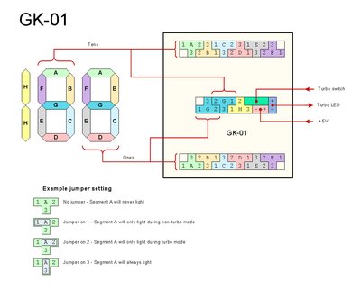
Hello! I got a pcchips M919 motherboard. It has two connectors turbo related. One turbo sw and one turbo led, both with two pins each.

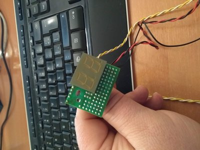
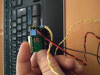
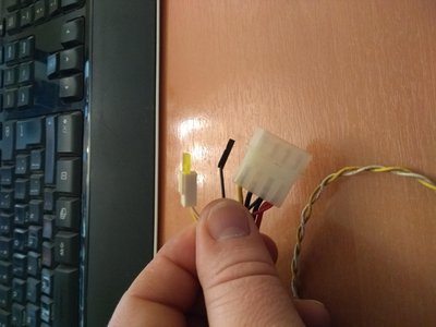
On the other hand i have a LED panel with a power connector to the PSU molex and an additional black single pin cable. Into the same LED panel comes out a yellow cable turbo led.

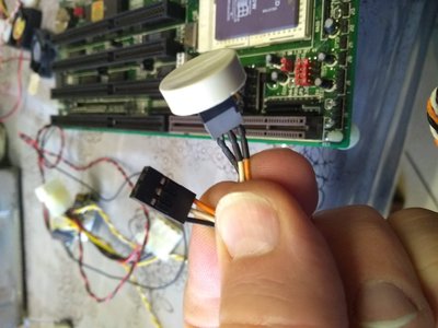
At last i got a turbo button switch with three cables.

If i plug the turbo button to the motherboard there is no link between the LED panel and the motherboard.

Anyone knows how i need to connect all this?

IMG_20180901_131106479.jpg
Filename
IMG_20180901_131106479.jpg
File size
900.38 KiB
Views
560 views
File comment
LED Panel
File license
Fair use/fair dealing exception
IMG_20180901_131124108.jpg
Filename
IMG_20180901_131124108.jpg
File size
422 KiB
Views
560 views
File comment
LED Panel Back
File license
Fair use/fair dealing exception
IMG_20180901_131152375.jpg
Filename
IMG_20180901_131152375.jpg
File size
899.76 KiB
Views
560 views
File comment
LED Panel cables
File license
Fair use/fair dealing exception
IMG_20180901_123550975.jpg
Filename
IMG_20180901_123550975.jpg
File size
572.07 KiB
Views
560 views
File comment
Turbo button
File license
Fair use/fair dealing exception

Thanks!

Follow me on twitter @cristian. 🤣

Reply 1 of 4, by PARKE

User metadata
Rank Oldbie
Rank
Oldbie

For 'original' connectivity you need a turbo switch with al least 2x2 wires - two going to the display and two going to the motherboard. The allround solution for all types of motherboards came with 2x3 wires of wich (again) two were going to the display and two going to the motherboard - which wires to connect depends on whether your motherboard is default running in turbo mode or default running in non-turbo. The yellow/white wires for the turbo led can be connected via the motherboard or via the display. The 'original' 2x3 wire button looks like this:
http://www.suntekpc.com/htm-2/power-switch-pu … urbo-3p3c-2.htm
In your case you need to solder at least two extra wires at the opposite side of the switch

Reply 3 of 4, by PARKE

User metadata
Rank Oldbie
Rank
Oldbie

Normally you should find three sets of pins for connectivity like as in this example:

LED display - GK-01.jpg
Filename
LED display - GK-01.jpg
File size
246.15 KiB
Views
535 views
File license
Fair use/fair dealing exception

The three pins for the turbo switch -may- be marked with the letters: T G N or L C H

Reply 4 of 4, by Vikingo

User metadata
Rank Newbie
Rank
Newbie

Thanks to all! I managed to make it work. The cables should not be connected as I had found them.

Try and error solved the problem.

Follow me on twitter @cristian. 🤣