There're 2 types of 7-segment LED modules, common anode and common cathode. You'll need to find out which type it is. Here is a pinout diagram that might or might not match your module.
The attachment HTB11bIoLFXXXXapXXXX760XFXXXT.png is no longer available
The turbo LED circuit is just a common emitter circuit like this:
The attachment LED-driver-circuit.png is no longer available
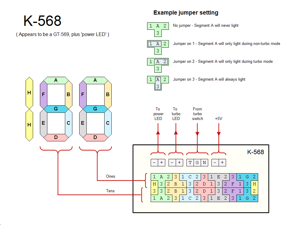
The jumpers will determine the segment is either always on, always off, or control by the turbo LED circuit. What you need to do is first draw out the turbo and non turbo digits that you like. Then look at the segments: if it is present in both turbo and non turbo, it is always on (connect to +5V). If on the other hand it is absent in both, then it is always off (no connection). If on in one and off in the other or vice versa, then it needs to be controlled by the turbo LED circuit. You'll need to find out on your 7-segment PCB which header pin position is for always on, always off, or controlled.
From simple tracing of the connections on your 7-segment PCB, it looks like this:
The attachment front.jpg is no longer available
I've drawn out just a few, the rest are just repetition. So it has a centre post and 3 possible jumper position: left, right, or vertical. The left & right look like controlled by turbo LED circuit (either on or off when turbo is active). The vertical position looks like +5V. But I couldn't see the traces at the other side (obscured by the header block) so I could be wrong, and you'll need to trace them with a multimeter.
Slow down your CPU with CPUSPD for DOS retro gaming.
