VOGONS


Reply 60 of 150, by RayeR

User metadata
Rank Oldbie
Rank
Oldbie

A looked in DS again, IOs are not 3,3V tolerant except CLK input where it is explicitly mentioned. For other inputs the maximum is VIO+0,3V so if someone use separate VIO regulator at 2,6V then maximum on input would be +0.3 = 3.0V, still over limit of 3.3V. Reasonable compromise would be set VIO at 3.0V then input can take 3.3V and it would be under abs. maximum. That nobody sees his overvolted CPU failing is good but doesn't mean there's no long term degradation of internal structures. Of course no problem for occasional hobbyst.

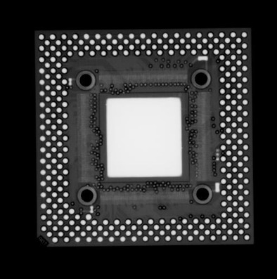
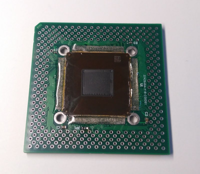
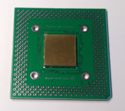
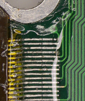
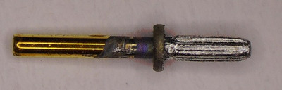
So now I managed to solder a copper IHS (I used 2mm thick Cu plate cut from a sheet) on top side and hope it also melted the paste under CPU core, without pin foil popping off the PCB (fused by epoxy). Then only pin work remains... I added some macros. I inspected the PPGA370 pin and I can see that the part fitted inside PPGA370 interposer has groovy surface, not smooth. So it seems that pins was pressed with a high force inside interposer vias and then soldered just for secure/better conductivity. As I have larger holes in my interposer it fits easily.

Attachments

Gigabyte GA-P67-DS3-B3, Core i7-2600K @4,5GHz, 8GB DDR3, 128GB SSD, GTX970(GF7900GT), SB Audigy + YMF724F + DreamBlaster combo + LPC2ISA

Reply 61 of 150, by Sphere478

User metadata
Rank l33t++
Rank
l33t++

Oh wow, you are making a very nice product there! I like the adhesive strips

What did that side look like before the ihs?

Sphere's PCB projects.
-
Sphere’s socket 5/7 cpu collection.
-
SUCCESSFUL K6-2+ to K6-3+ Full Cache Enable Mod
-
Tyan S1564S to S1564D single to dual processor conversion (also s1563 and s1562)

Reply 62 of 150, by RayeR

User metadata
Rank Oldbie
Rank
Oldbie

On the top side I left unmasked copper area witch cca 200 tiny vias for thermal conduction. I apply solder paste, put IHS on and solder by hot air...

Gigabyte GA-P67-DS3-B3, Core i7-2600K @4,5GHz, 8GB DDR3, 128GB SSD, GTX970(GF7900GT), SB Audigy + YMF724F + DreamBlaster combo + LPC2ISA

Reply 63 of 150, by pentiumspeed

User metadata
Rank l33t
Rank
l33t

Next time, get some low temp metal collected from under the IHS of a large, cheap xeon CPU for the die solder bond.

Cheers,

Great Northern aka Canada.

Reply 64 of 150, by RayeR

User metadata
Rank Oldbie
Rank
Oldbie

Ah, I also have some low-temp solder paste (indium based?) but I don't belive it would be stable as old good Sn37Pb63... And I even didn't think about it as I don't use it for normal soldering...

Gigabyte GA-P67-DS3-B3, Core i7-2600K @4,5GHz, 8GB DDR3, 128GB SSD, GTX970(GF7900GT), SB Audigy + YMF724F + DreamBlaster combo + LPC2ISA

Reply 65 of 150, by Sphere478

User metadata
Rank l33t++
Rank
l33t++

Can you liquid metal or solder the core to the pcb?

Probably pointless but, would be cool.

Sphere's PCB projects.
-
Sphere’s socket 5/7 cpu collection.
-
SUCCESSFUL K6-2+ to K6-3+ Full Cache Enable Mod
-
Tyan S1564S to S1564D single to dual processor conversion (also s1563 and s1562)

Reply 66 of 150, by Sphere478

User metadata
Rank l33t++
Rank
l33t++

Hey, question, what if any of the tillamook mods did you incorporate into this, and where did you map bf2 to?

The best way to route the two bf2 pins would be to just link them together (intel bf2 and amd bf2) and give them a 1000 ohm pull up resistor

As for the other pins, may want to see if the same tillamook mods apply to your unit.

Re: Tillamook 266MHz and working L2 cache?

Sphere's PCB projects.
-
Sphere’s socket 5/7 cpu collection.
-
SUCCESSFUL K6-2+ to K6-3+ Full Cache Enable Mod
-
Tyan S1564S to S1564D single to dual processor conversion (also s1563 and s1562)

Reply 67 of 150, by RayeR

User metadata
Rank Oldbie
Rank
Oldbie

Damn, I'm wrecked. After soldering the PGA pins (it went quite well using precise socket as pins holder) I did the final test with multimeter and found shorts on both VCC2 and VCC3 to GND and also A13, A14 to GND. I cannot see anything wrong on the surface. Maybe it happen that during soldering of IHS some excesive metal leaked through vias to bottom side in the gap around the core and touched the golden traces on foil inner side (I should kapton tape it but didn't). I would need do x-ray image to prove it but as it's glued so I cannot fix it anyway...

Gigabyte GA-P67-DS3-B3, Core i7-2600K @4,5GHz, 8GB DDR3, 128GB SSD, GTX970(GF7900GT), SB Audigy + YMF724F + DreamBlaster combo + LPC2ISA

Reply 68 of 150, by rasz_pl

User metadata
Rank l33t
Rank
l33t
Sphere478 wrote on 2023-10-25, 02:19:

Can you liquid metal or solder the core to the pcb?

pentiumspeed wrote on 2023-10-24, 17:56:

Next time, get some low temp metal collected from under the IHS of a large, cheap xeon CPU for the die solder bond.

to immediately corrode copper? https://www.gamersnexus.net/guides/3362-how-l … -corrosion-test

bummer about shorts 🙁

Open Source AT&T Globalyst/NCR/FIC 486-GAC-2 proprietary Cache Module reproduction

Reply 69 of 150, by BitWrangler

User metadata
Rank l33t++
Rank
l33t++

Maybe try burning them out by applying power across, in case they are just thin whiskers or very thin points of contact.

Unicorn herding operations are proceeding, but all the totes of hens teeth and barrels of rocking horse poop give them plenty of hiding spots.

Reply 70 of 150, by pentiumspeed

User metadata
Rank l33t
Rank
l33t

Not that liquid metal. The low temp solder from cheap large xeon does not corrode! The gap in the silicone glue is air vent.

Cheers,

Great Northern aka Canada.

Reply 71 of 150, by RayeR

User metadata
Rank Oldbie
Rank
Oldbie

I pleased a friend who took a few x-ray images, not much hi-res but we found that thick IHS makes core and foil wires invisible.
So I desoldered IHS and let him x-ray it again. I also tried to suck off as much melted solder as possible by litz wire - it completly cleaned the vias but all shorts remains. I guess solder blob somewhere on golden foil wires....

Attachments

Gigabyte GA-P67-DS3-B3, Core i7-2600K @4,5GHz, 8GB DDR3, 128GB SSD, GTX970(GF7900GT), SB Audigy + YMF724F + DreamBlaster combo + LPC2ISA

Reply 72 of 150, by Sphere478

User metadata
Rank l33t++
Rank
l33t++

Damn. Do you have an idea of how to fix? Or start all over?

Good idea about kapton for next time!

Sphere's PCB projects.
-
Sphere’s socket 5/7 cpu collection.
-
SUCCESSFUL K6-2+ to K6-3+ Full Cache Enable Mod
-
Tyan S1564S to S1564D single to dual processor conversion (also s1563 and s1562)

Reply 73 of 150, by RayeR

User metadata
Rank Oldbie
Rank
Oldbie

The only chance is carefully grinding off the PCB area around CPU core by Dremel from top side, then suck off the excessive solder from gold foil wires. I cannot take the CPU off, the epoxy glue proved very good thermal stability 😜 I hope that x-ray image could help me localize the possible short so only small hole would be needed instead of grinding the entire center area. Yes, better insulation preparation with kapton tape (I taped only PCB surface with traces that could get in touch with foil) or epoxy varnish on CPU bottom side could save this pain, now I-idiot know for future, but not going to reproduce it anyway. 4 PBCs left for someone brave...

Gigabyte GA-P67-DS3-B3, Core i7-2600K @4,5GHz, 8GB DDR3, 128GB SSD, GTX970(GF7900GT), SB Audigy + YMF724F + DreamBlaster combo + LPC2ISA

Reply 74 of 150, by Sphere478

User metadata
Rank l33t++
Rank
l33t++

So you won’t try again? 🙁

Sphere's PCB projects.
-
Sphere’s socket 5/7 cpu collection.
-
SUCCESSFUL K6-2+ to K6-3+ Full Cache Enable Mod
-
Tyan S1564S to S1564D single to dual processor conversion (also s1563 and s1562)

Reply 75 of 150, by RayeR

User metadata
Rank Oldbie
Rank
Oldbie

I have only one such CPU and I cannot remove it from current PCB without destoying glued pins.

Gigabyte GA-P67-DS3-B3, Core i7-2600K @4,5GHz, 8GB DDR3, 128GB SSD, GTX970(GF7900GT), SB Audigy + YMF724F + DreamBlaster combo + LPC2ISA

Reply 76 of 150, by BitWrangler

User metadata
Rank l33t++
Rank
l33t++

I'd be doing something like belt sanding the PCB off 🤣

Unicorn herding operations are proceeding, but all the totes of hens teeth and barrels of rocking horse poop give them plenty of hiding spots.

Reply 77 of 150, by Sphere478

User metadata
Rank l33t++
Rank
l33t++

I had a thought, when soldering the ihs, perhaps it should be done upside down with a clamp so all solder blobs flow down, if trying to solder the core I mean, if using paste, just do it before placing the core

As for your current cpu, I think perhaps you will have to make it a display piece or destructively remove the current cpu in order to place another one

Have you ordered more?

Sphere's PCB projects.
-
Sphere’s socket 5/7 cpu collection.
-
SUCCESSFUL K6-2+ to K6-3+ Full Cache Enable Mod
-
Tyan S1564S to S1564D single to dual processor conversion (also s1563 and s1562)

Reply 78 of 150, by RayeR

User metadata
Rank Oldbie
Rank
Oldbie

More of what? The interposer PCBs was made in count of 5pcs because it's a minimum Qty that JLCPCB do. The CPU I have was only one and I desolder it from a wreck of old Compaq Armada laptop (my 1st post). I was quite surprised by this as I never seen such package before and expected a socketed cpu but then I said it would be a challenge to make it working, even when PGA tillamooks are now hard to buy... Yes, soldering IHS upside down would.probably prevent this issue, maybe someone else take a lesson from this...

I'm waiting for next x-ray images so I hope it will tell me more if/where/how to fix it.

BTW it's a pitty nobody pointed me to old L2 cache issues and solution that I could add to this interposer. At least there are 2 things to be added: VCC2DET for proper dual.VRM detection and ADSC copy signals for cache...

Gigabyte GA-P67-DS3-B3, Core i7-2600K @4,5GHz, 8GB DDR3, 128GB SSD, GTX970(GF7900GT), SB Audigy + YMF724F + DreamBlaster combo + LPC2ISA

Reply 79 of 150, by Sphere478

User metadata
Rank l33t++
Rank
l33t++

Another cpu

They are all over EBay.

Sphere's PCB projects.
-
Sphere’s socket 5/7 cpu collection.
-
SUCCESSFUL K6-2+ to K6-3+ Full Cache Enable Mod
-
Tyan S1564S to S1564D single to dual processor conversion (also s1563 and s1562)