VOGONS


Reply 40 of 52, by rasz_pl
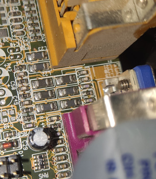
User metadata
Rank l33t
Rank
l33t
smoke86 wrote on 2022-10-23, 15:36:

Yes, pins 1 and 2 are indeed shorted (I know there shouldn't be a short there). I did not confuse pins, the short is also present on the solder joints of VGA connector.

VGA-Pinouts-16fe4wk.png
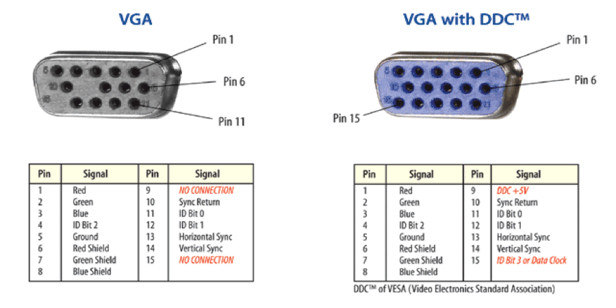
pin 6 is always closest to one side while pins 5 and 15 to the other

Even if measured correctly still wouldnt explain the problem entirely because third video channel can produce video on its own. But its a start.
Are L4 L20 L22 shorted to ground by any chance?

smoke86 wrote on 2022-10-23, 15:36:

I don't understand what you ment by "do the "L44 L45 L46 and ending on the other side with L47 L48 L49 L50 L52", shall I check continuity with pin 13 and 14 with those inductors?
I checked it, but no continuity to pins 13 and 14.

I mean do the VGA pin x to ALL inductors, not just the ones close to the VGA socket. All 2-4 19-23 44-50 52. While we are at it you can also do all small resistors and caps near the chipset.
I feel now telling you to do X without explaining reason for it was the mistake. You want to draw a diagram (map) between VGA pins, all the elements between, and the chipset. We cant measure chipset pins directly (bga package), so we need to find the closest elements with those signals. The next step will be desoldering those elements closest to the chipset and checking which side has the problem. There are several modes of failure possible here
1 one/all chipset outputs are blown, ESD damage can do this
2 Vref is bad, cant do anything about it as its internal in the chipset (just like in Trident 3D)
Someone dropped something on the board and cracked one of SMD elements. Old solder joint cracked. those would:
3 open/partially damaged inductor or resistor means no signal. Seems unlikely in this case, you would have to be super unlucky to have all three R G B channels damaged in same way. I think damaged H or V would result in monitor unable to sync picture at all.
4 small smd capacitors with mechanical damage tend to short circuit

"but no continuity to pins 13 and 14 anywhere" those might only go thru resistors near the chipset like in the GA-5VMM diagram.

smoke86 wrote on 2022-10-23, 15:36:

You can't see a problem with geometry, because picture is little wavy and it is not possible to capture it with camera, especially on static photo.

wavy picture could be caused by very low H V signal levels, maybe Chipset is unable to sustain proper levels on all other outputs if one of them is shorted to ground?

Open Source AT&T Globalyst/NCR/FIC 486-GAC-2 proprietary Cache Module reproduction

Reply 41 of 52, by smoke86

User metadata
Rank Member
Rank
Member

One of sides of L22 is shorted to ground.
I will try to make a diagram, but it will take me some time.
I actually made a loop of solder wick in order to extend range of my multimeter when it comes to continuity. I tried touching every single solder joints on the board, when searching for vga's pin 13 and 14, but no luck. But then I remembered that we are dealing with multilayer board, is it possible that those two are running inside the board directly to chipset?

Reply 42 of 52, by Roman555

User metadata
Rank Oldbie
Rank
Oldbie
smoke86 wrote on 2022-10-24, 16:14:

One of sides of L22 is shorted to ground.
I will try to make a diagram, but it will take me some time.
I actually made a loop of solder wick in order to extend range of my multimeter when it comes to continuity. I tried touching every single solder joints on the board, when searching for vga's pin 13 and 14, but no luck. But then I remembered that we are dealing with multilayer board, is it possible that those two are running inside the board directly to chipset?

1) If only one of sides of L22 is shorted to ground then L22 is broken. If you measure continuity of L22 in diode mode the multimeter doesn't beep?
2) Yes, the pin 13 and 14 can be connected directly into the chip. Although the multimeter (diode mode to the GND) should show something (not discontinuity, I mean) and similar for both pins, I think

[ MS6168/PII-350/YMF754/98SE ]
[ 775i65G/E5500/9800Pro/Vortex2/ME ]

Reply 43 of 52, by smoke86

User metadata
Rank Member
Rank
Member

@Roman555
No, it does not beep.
Shall I replace it with exactly the same inductor? Or can I replace it with similar one just for testing?
Multimeter shows some readings on multiple components when in continuity mode with pins 13 and 14, but no direct connection.
I found it unusual that ground on VGA does not have continuity to ground on LPT (maybe because of abovementioned short).

Reply 46 of 52, by pentiumspeed

User metadata
Rank l33t
Rank
l33t

L22 is either vertical or horizontal signal output. You might meant L21? That's one of color due to group of threes, one each for color and there 3 more in group as well.

You must expect 75 ohms resistors on all of the RGB outputs and are grounded to match impedance of the 75 ohm coax in the cable. Measure this way on one of color outputs to ground and you will
read 75 ohms.

"Lxx" is a inductor to filter out high frequency noise and will measure shorted when measured end to end of each inductor.

Edited, I was mistaken about the termination resistor.

Cheers,

Last edited by pentiumspeed on 2022-10-25, 16:43. Edited 1 time in total.

Great Northern aka Canada.

Reply 48 of 52, by pentiumspeed

User metadata
Rank l33t
Rank
l33t

Yea you need to measure L22 end to end to make sure it is open or conducting (they will read short due to being inductor and is normal if end to end).

And L22 is for either vertical or horizontal signal output which are not supposed to be shorted to ground and does not having impedance resistors. L22 and L23 and is fine because you do get image means vertical and horizontal pulses outputs are working.

Anything less than 10 ohms is short depending on circuit that were designed for. For example CPU power circuit or GPU card power circuit they read very low around 2 ohms or so is normal.

Dim image is weak video outputs on all RGB (red, green and blue) P-P voltage is too low. RAMDAC part does have current reference pin to set the RGB outputs at correct current with the impedance termination resistors in use

Cheers,

Great Northern aka Canada.

Reply 49 of 52, by smoke86

User metadata
Rank Member
Rank
Member

L22 measured end to end reads 38 ohms (like some other inductors on that board).
My guess is that the short may be elsewhere; L19 is also shorted to the ground on one side (that one reads 38 ohms end to end).

Reply 50 of 52, by rasz_pl

User metadata
Rank l33t
Rank
l33t
smoke86 wrote on 2022-10-24, 20:22:

L22 measured end to end reads 38 ohms (like some other inductors on that board).
My guess is that the short may be elsewhere; L19 is also shorted to the ground on one side (that one reads 38 ohms end to end).

No inductors measure 38 ohms. Inductor is just a coil of wires. 1 kilometer of 1mm2 thick copper wire has 17 ohms resistance.
Remember how I told you three times now to start drawing a map of connections?

I dont see you finding what L22 is wired to. It sure looks like its going under LPT connector. But if its broken desolder it, you can keep adding solder until both ends are connected, this will let you take it off with regular iron.

pentiumspeed wrote on 2022-10-24, 20:03:

Yea you need to measure L22 end to end to make sure it is open or conducting (they will read short due to being inductor and is normal if end to end).

you came in late to the party, we are past checking that 😀

pentiumspeed wrote on 2022-10-24, 20:03:

And L22 is for either vertical or horizontal

smoke86 apparently already verified thats not the case 🙁

Open Source AT&T Globalyst/NCR/FIC 486-GAC-2 proprietary Cache Module reproduction

Reply 51 of 52, by Roman555

User metadata
Rank Oldbie
Rank
Oldbie
smoke86 wrote on 2022-10-24, 18:42:
@Roman555 No, it does not beep. Shall I replace it with exactly the same inductor? Or can I replace it with similar one just for […]
Show full quote

@Roman555
No, it does not beep.
Shall I replace it with exactly the same inductor? Or can I replace it with similar one just for testing?
Multimeter shows some readings on multiple components when in continuity mode with pins 13 and 14, but no direct connection.
I found it unusual that ground on VGA does not have continuity to ground on LPT (maybe because of abovementioned short).

1) It's too early to replace the inductor because, as I understood, one of its side has a short circuit to GND. It may get broken again.
2) If the multimeter shows some readings then pin 13 and 14 are OK I think.

As experiment I measured a VGA of a i815 mainboard. My multimeter (diode mode) showed 78 for pins 1-3 and about 790 for pins 13-14 (red pin to GND of mounting hole)

P.S. My guesses about purpose of components are on the picture.
As you can see L22 is connected to GND rail.
P.P.S. Maybe L22 divides (or connects) decouples different GNDs (analog and digital). And if L22 is broken then there's no an important connection.
smoke86, can you discover whether pin 5 of VGA is connected to either pin of L22 ?

mvp4-vga-2-guess.jpg vga-gnd.png

[ MS6168/PII-350/YMF754/98SE ]
[ 775i65G/E5500/9800Pro/Vortex2/ME ]