Reply 40 of 52, by rasz_pl
smoke86 wrote on 2022-10-23, 15:36:Yes, pins 1 and 2 are indeed shorted (I know there shouldn't be a short there). I did not confuse pins, the short is also present on the solder joints of VGA connector.

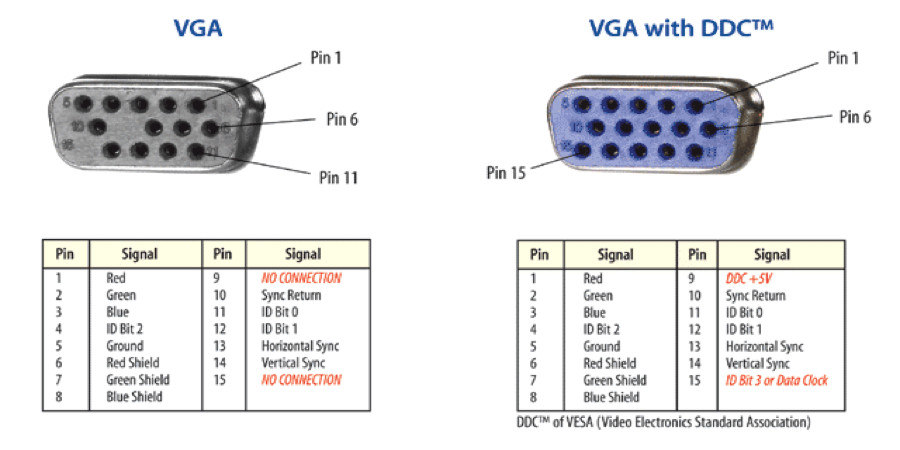
pin 6 is always closest to one side while pins 5 and 15 to the other
Even if measured correctly still wouldnt explain the problem entirely because third video channel can produce video on its own. But its a start.
Are L4 L20 L22 shorted to ground by any chance?
smoke86 wrote on 2022-10-23, 15:36:I don't understand what you ment by "do the "L44 L45 L46 and ending on the other side with L47 L48 L49 L50 L52", shall I check continuity with pin 13 and 14 with those inductors?
I checked it, but no continuity to pins 13 and 14.
I mean do the VGA pin x to ALL inductors, not just the ones close to the VGA socket. All 2-4 19-23 44-50 52. While we are at it you can also do all small resistors and caps near the chipset.
I feel now telling you to do X without explaining reason for it was the mistake. You want to draw a diagram (map) between VGA pins, all the elements between, and the chipset. We cant measure chipset pins directly (bga package), so we need to find the closest elements with those signals. The next step will be desoldering those elements closest to the chipset and checking which side has the problem. There are several modes of failure possible here
1 one/all chipset outputs are blown, ESD damage can do this
2 Vref is bad, cant do anything about it as its internal in the chipset (just like in Trident 3D)
Someone dropped something on the board and cracked one of SMD elements. Old solder joint cracked. those would:
3 open/partially damaged inductor or resistor means no signal. Seems unlikely in this case, you would have to be super unlucky to have all three R G B channels damaged in same way. I think damaged H or V would result in monitor unable to sync picture at all.
4 small smd capacitors with mechanical damage tend to short circuit
"but no continuity to pins 13 and 14 anywhere" those might only go thru resistors near the chipset like in the GA-5VMM diagram.
smoke86 wrote on 2022-10-23, 15:36:You can't see a problem with geometry, because picture is little wavy and it is not possible to capture it with camera, especially on static photo.
wavy picture could be caused by very low H V signal levels, maybe Chipset is unable to sustain proper levels on all other outputs if one of them is shorted to ground?
https://github.com/raszpl/FIC-486-GAC-2-Cache-Module for AT&T Globalyst
https://github.com/raszpl/386RC-16 memory board
https://github.com/raszpl/440BX Reference Design adapted to Kicad
https://github.com/raszpl/Zenith_ZBIOS MFM-300 Monitor

