VOGONS


First post, by Socket3

User metadata
Rank Oldbie
Rank
Oldbie

Hi guys and gals. I'm trying to put together a (nice) slot A machine, but I don't have a working motherboard. Out of the two Slot A boards I own one is unstable (ECS K7ASA AMD 750 chipset, no ISA) and the other let out magic smoke - the MSI this thread is about.

I'd really love to get the MSI going since the ECS is slow, unstable and is very very limited in features and BIOS options. It will only run stable(ish) at AGP 1X speeds and it won't let me touch memory timings or speed in bios.

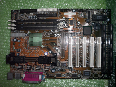
The MSI is a MS-6167, same AMD Irongate 750 chipset as the ECS, but unlike the latter it has a full featured bios and two ISA slots. I got the MSI from the same scrap / recycling center I get most of my stuff from, and it came with a 750MHz Athlon in the slot.

Physically, the board looks excellent. To broken traces, and it wasn't corroded or particularly dirty. I gave it a good cleaning and attempted to fire it up, but she will not post and a few seconds after powering it up it let out "a smell". Not burning, but like something metallic was getting really hot. Here's a pic of the board with the tiny black heatsinks that normally sit on the mosfets removed:

board.jpg
Filename
board.jpg
File size
973.08 KiB
Views
391 views
File license
CC-BY-4.0

I inspected the board again after that, no visible signs of charring or burning anywhere. So I gave it another good cleaning - particularly in the VRM area where there was some white stuff all around the legs of the fets and voltage regulator's pins, and had another go. I also took out my IR thermometer and started measuring temps of the mosfets and surrounding PCB. I found the following:

FETS.jpg
Filename
FETS.jpg
File size
830.42 KiB
Views
391 views
File license
CC-BY-4.0

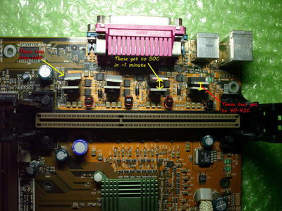
Two pairs of mosfets got pretty hot in 1 minute after powering up the board, and the bottom most pair stayed cold the whole time - click on the picture for more details.

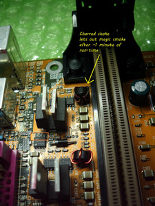
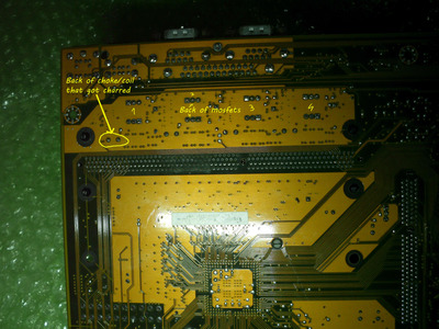
After letting the board run for 1-2 minutes to try and figure out what is getting hot and where, I noticed the smell again - smelled like hot metal - and a tiny amount of smoke. Turns out the top most choke / coil gets really hot, and it got charred. I pulled the power again, and had a look at the back. The back of the board was quite hot, about 80C, right where the choke is soldered in, but there's no visible damage. No burnt trace or charring. Here is the choke in question - you can see it's charred - but only the copper, the PCB around the choke itself is perfectly fine:

choke.jpg
Filename
choke.jpg
File size
784.76 KiB
Views
391 views
File license
CC-BY-4.0

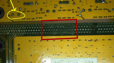
And here is the back of the board:

back.jpg
Filename
back.jpg
File size
854.91 KiB
Views
391 views
File license
CC-BY-4.0

My question is - is the choke itself shorted - perhaps the enamel came off and the copper wires are touching somewhere - or are some of the mosfets bad and are letting trough 5 or 12V into the choke?

I pulled out the test CPU - a 550MHz athlon, put it in my working but unstable ECS board and it posted, so it seems the CPU was not damaged...

After the 3 diagnostic attempts described above, the board will not wait for the power button to be pressed to power on, it will power up as soon as I turn the PSU on. It did not do that before. Possible short circuit?

If the choke itself is the cause, how can I find an identical replacement? Are there any markings on these anywhere?

Any help would be greatly appreciated, I'd really love to get this board running. Slot A hardware has been on my list for over 10 years now, and these 2 boards along with 3 CPUs are all I've been able to come across so far. I can't afford to spend 100+ usd + 50$ for shipping on a working kit from ebay, so that's out of the question.

Reply 1 of 5, by Roman555

User metadata
Rank Oldbie
Rank
Oldbie

The place looks bad. I suppose the choke becomes hot because of short circuit in its load. It can be discovered by measurement using a multimeter.

Attachments

  • Filename
    SC1144-SC1405-eval.PDF
    File size
    44.42 KiB
    Downloads
    27 downloads
    File license
    Fair use/fair dealing exception
  • ms6167-back.jpg
    Filename
    ms6167-back.jpg
    File size
    160.24 KiB
    Views
    365 views
    File license
    Public domain

[ MS6168/PII-350/YMF754/98SE ]
[ 775i65G/E5500/9800Pro/Vortex2/ME ]

Reply 2 of 5, by Socket3

User metadata
Rank Oldbie
Rank
Oldbie

it looks much worse then it is. There used to be a sticker there, that's glue residue. I checked for shorts in that area, couldn't find any. I've since cleaned the leftover glue off with IPA and a toothbrush.

Last edited by Socket3 on 2023-05-13, 06:52. Edited 1 time in total.

Reply 3 of 5, by bogdanpaulb

User metadata
Rank Member
Rank
Member

Check the sc1405 mos fet driver (oxide), a oscilloscope would be nice. You can try and remove parts from that 'phase' and try to run the board only on 3 phases, it should post if everything else is ok (no prime95 or extensive loads recommended thou!). Here you have a general application schematic for the circuitry at page 7, the only difference is that on this board they added some FDS6612A's in 'between'. https://pdf1.alldatasheet.com/datasheet-pdf/v … ECH/SC1405.html, here you have the 'extra'mos fets https://datasheetspdf.com/pdf-file/210936/Fai … ctor/FDS6612A/1.

Attachments

  • oxide.jpg
    Filename
    oxide.jpg
    File size
    801.91 KiB
    Views
    323 views
    File license
    Fair use/fair dealing exception

Reply 4 of 5, by Roman555

User metadata
Rank Oldbie
Rank
Oldbie
Socket3 wrote on 2023-05-12, 16:53:

it looks much worse then it is. There used to be a sticker there, that's glue residue. I checked for shorts, couldn't find any. I've since cleaned the leftover glue off with IPA and a toothbrush.

I would check electrolytic capacitors in Vcore circuit. They could lost their characteristics. At that time MSI usually used bad electrolytic capacitors.
As bogdanpaulb has mentioned an oscilloscope would show you quality of signals in VRM. But if you don't have an ESR-meter or/and an oscilloscope it's better just recap.

P.S. Found your post Re: Unstable Slot-A build.
So you did replace capacitors. Then yes, maybe something wrong with this phase. Once I had similar problem but I didn't find exact faulty component. And finally desoldered MOSFETs and a choke. That mainboard worked without one phase although I didn't test it heavily.

[ MS6168/PII-350/YMF754/98SE ]
[ 775i65G/E5500/9800Pro/Vortex2/ME ]

Reply 5 of 5, by Socket3

User metadata
Rank Oldbie
Rank
Oldbie
bogdanpaulb wrote on 2023-05-12, 18:23:

Check the sc1405 mos fet driver (oxide), a oscilloscope would be nice. You can try and remove parts from that 'phase' and try to run the board only on 3 phases, it should post if everything else is ok (no prime95 or extensive loads recommended thou!). Here you have a general application schematic for the circuitry at page 7, the only difference is that on this board they added some FDS6612A's in 'between'. https://pdf1.alldatasheet.com/datasheet-pdf/v … ECH/SC1405.html, here you have the 'extra'mos fets https://datasheetspdf.com/pdf-file/210936/Fai … ctor/FDS6612A/1.

Unfortunately, I don't own an oscilloscope... it's on my to buy list, together with an electronics microscope, but I can't afford them at the moment. I had a look at the linear regulators and surrounding circuitry with a continuity meter, and compared the results to a working board with similar construction and I think the linear regulators are shorted to ground... I did notice the gunk in between the legs of several mosfets and I've been scrubbing the stuff off for days. Despite how it looks in the picture the residue is not causing a short, at least according to my continuity testing. I'll add vinegar again on that fet and scrub some more just in case. If it still won't come off I'll desolder the part and clean the pads with flux.

I'll do just that, start pulling parts, and see if I can eliminate the short. I was thinking of starting with the regulators since they are much easier to remove and resolder then the MOSFETs, and go from there.

Mersi mult!

Roman555 wrote on 2023-05-12, 20:50:
I would check electrolytic capacitors in Vcore circuit. They could lost their characteristics. At that time MSI usually used bad […]
Show full quote
Socket3 wrote on 2023-05-12, 16:53:

it looks much worse then it is. There used to be a sticker there, that's glue residue. I checked for shorts, couldn't find any. I've since cleaned the leftover glue off with IPA and a toothbrush.

I would check electrolytic capacitors in Vcore circuit. They could lost their characteristics. At that time MSI usually used bad electrolytic capacitors.
As bogdanpaulb has mentioned an oscilloscope would show you quality of signals in VRM. But if you don't have an ESR-meter or/and an oscilloscope it's better just recap.

P.S. Found your post Re: Unstable Slot-A build.
So you did replace capacitors. Then yes, maybe something wrong with this phase. Once I had similar problem but I didn't find exact faulty component. And finally desoldered MOSFETs and a choke. That mainboard worked without one phase although I didn't test it heavily.

Thanks for the advice!