VOGONS


First post, by uebersoldat

User metadata
Rank Newbie
Rank
Newbie

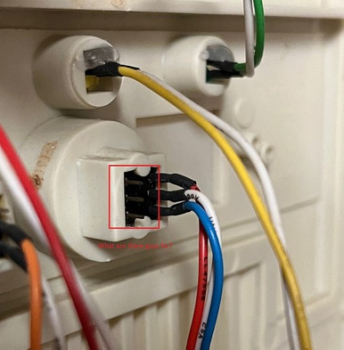
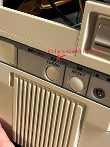
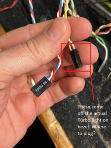
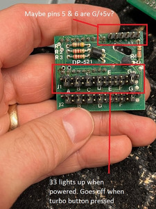
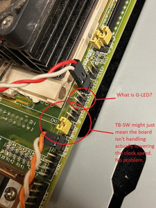
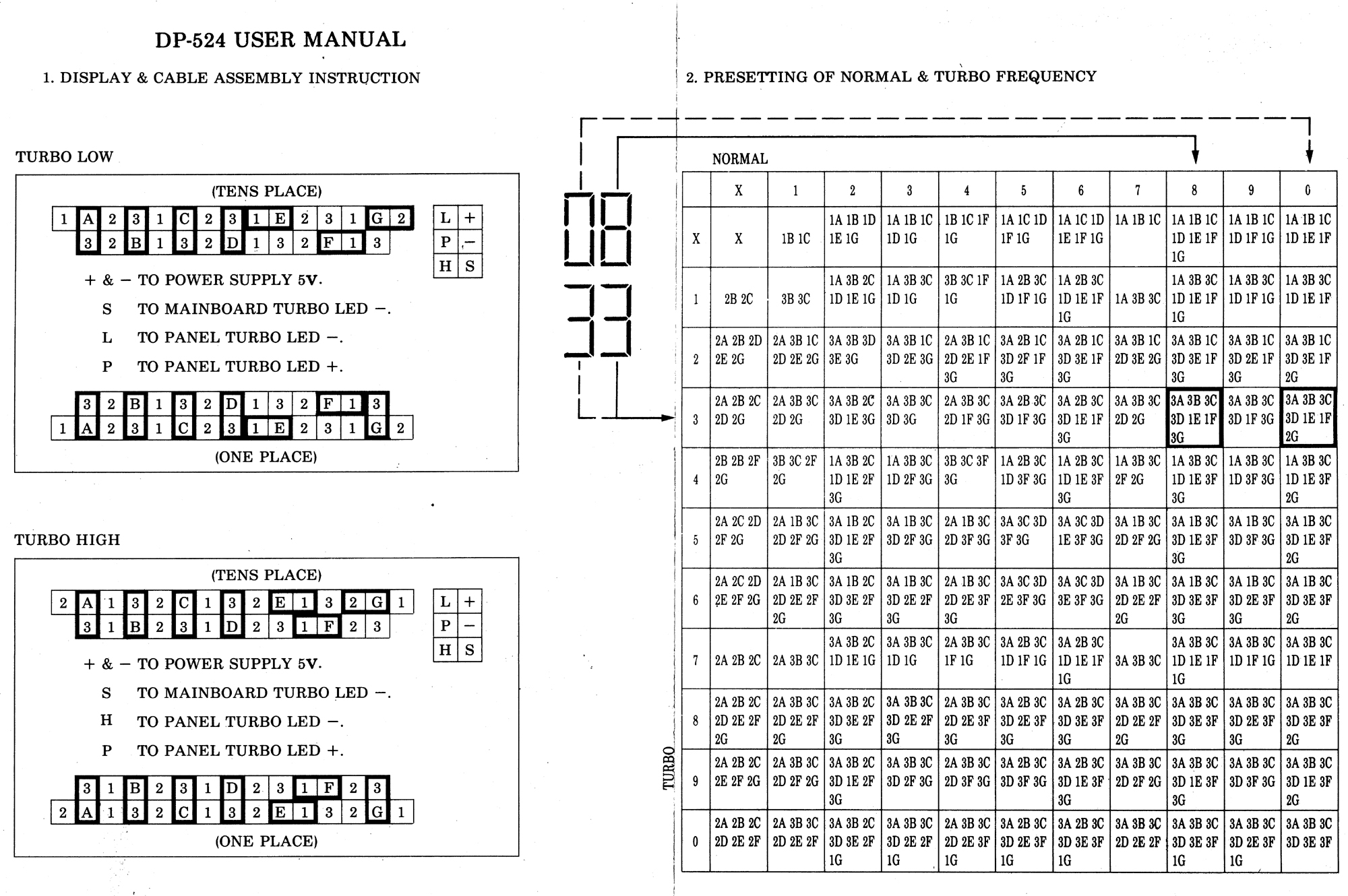
Help! I have been messing with this all evening and I'm not real sure I've got this figured out but I can get 33 to display when I run a hot and ground wire to pins 5 and 6 on the little LED board. It gets really hot though so I'm not sure if running the wire from a molex power adapter is a good idea. Anyway, I can't identify this mobo and can't find wiring specs on the LED board and so I'm hoping for a little understand of how this typical generic AT case wires into the LED/Mobo. What are the three wires coming off the turbo button on the bezel? What are the 3 extra pins there for next to them? How does the two-wire LED for the turbo connect? (can't get it to light up). Are the resistors on the board supposed to get too hot to touch?

Thank you so much for any expertise you can provide! Really looking forward to getting this retro battlestation going 😀

Attachments

  • 5.JPG
    Filename
    5.JPG
    File size
    50.17 KiB
    Views
    459 views
    File license
    CC-BY-4.0
  • 4.JPG
    Filename
    4.JPG
    File size
    59.43 KiB
    Views
    459 views
    File license
    CC-BY-4.0
  • 3.JPG
    Filename
    3.JPG
    File size
    63.52 KiB
    Views
    459 views
    File license
    CC-BY-4.0
  • 2.JPG
    Filename
    2.JPG
    File size
    86.3 KiB
    Views
    459 views
    File license
    CC-BY-4.0
  • 1.JPG
    Filename
    1.JPG
    File size
    141.25 KiB
    Views
    459 views
    File license
    CC-BY-4.0

Reply 1 of 17, by analog_programmer

User metadata
Rank Oldbie
Rank
Oldbie

Remove TB-SW jumper and connect there TURBO SW connector. Try white and blue wires and white and red which combination will be for button pressed/depressed "turbo on". Turbo LED on case goes to TB-LED on the mobo. G-LED maybe comes from "Green LED" if this board supports some power saving features, leave it alone (I don't see any suitable LED on the case to be connected to it). "33" on the segment display has nothing to do with actual CPU speed - this is set manually by jumpers. Search the internet how to set and connect this model segment display.

P.S. And maybe you're missing two-wire connector from 2P2D "turbo switch" on the case to MB TURBO SW connector.

Last edited by analog_programmer on 2024-03-06, 13:48. Edited 1 time in total.

from СМ630 to Ryzen gen. 3
engineer's five pennies: this world goes south since everything's run by financiers and economists
this isn't voice chat, yet some people, overusing online communications, "talk" and "hear voices"

Reply 2 of 17, by PARKE

User metadata
Rank Oldbie
Rank
Oldbie

For a fully functional config (how it was meant to work) you need two wires coming from the turbo switch that signal the motherboard plus three wires coming from the turbo switch to signal the display simultaneously.
http://www.suntekpc.com/htm-2/power-switch-pu … urbo-3p3c-2.htm

The jumpers on the display follow this system:

LEDsimp2b.jpg
Filename
LEDsimp2b.jpg
File size
55.77 KiB
Views
412 views
File license
Fair use/fair dealing exception

Reply 3 of 17, by snufkin

User metadata
Rank Oldbie
Rank
Oldbie

There's a diagram for the DP-524, which might be similar to the DP-521: https://www.minuszerodegrees.net/led_speed_di … 0-%20DP-524.jpg

The three wires coming from the turbo switch will have two that are shorted/connected together, either Red-White or Blue-White, depending on the switch position. If it fits then that 3-pin connector should go to the 2-pin TB-SW on the motherboard so that the switch can either short or open the header pins. It shouldn't matter whether it's the Red-White or Blue-White that connect. That should let you switch the motherboard between normal and slow.

Ignoring the display for the moment, the next thing to check is the Turbo LED. Connect the 2-pin Yellow-White connector to the 2-pin TB-LED header. See if the LED turns on when you press the Turbo the switch. If it doesn't then turn the connector on the motherboard around (so the pin that went to Yellow goes to White instead). If the LED still doesn't turn on then that means there's probably a problem with the turbo switch, the LED or the motherboard.

If it does work then you know the motherboard is switching and the turbo header works.

For the display, in one of your photos you say that the display turns off when you push the turbo button. What wires did you have connected where?

Reply 4 of 17, by analog_programmer

User metadata
Rank Oldbie
Rank
Oldbie

Maybe this picture will help to clarify the case (taken from another forum's thread):

turbo_switching_1.jpg

from СМ630 to Ryzen gen. 3
engineer's five pennies: this world goes south since everything's run by financiers and economists
this isn't voice chat, yet some people, overusing online communications, "talk" and "hear voices"

Reply 5 of 17, by uebersoldat

User metadata
Rank Newbie
Rank
Newbie
snufkin wrote on 2024-03-06, 13:58:

For the display, in one of your photos you say that the display turns off when you push the turbo button. What wires did you have connected where?

I'm going to double-check tonight but I believe I had the Red-White-Blue connected to from the back of the switch to pins 1-2-3 respectively on the LED board. I don't understand electricity as well as I should but I believe pins 5 and 6 are the ground and 5v. I tried the power connector on pins 1 and 2 and the thing started smelling and a wisp of smoke came from somewhere. Oops! Guess that's not going to work! The board still seemed to work ok after that though. Plus I have another identical LED board that is operating the same way. The 33 lights up bright green with the aforementioned wiring.

Reply 6 of 17, by uebersoldat

User metadata
Rank Newbie
Rank
Newbie
analog_programmer wrote on 2024-03-06, 12:21:

Remove TB-SW jumper and connect there TURBO SW connector. Try white and blue wires and white and red which combination will be for button pressed/depressed "turbo on". Turbo LED on case goes to TB-LED on the mobo. G-LED maybe comes from "Green LED" if this board supports some power saving features, leave it alone (I don't see any suitable LED on the case to be connected to it). "33" on the segment display has nothing to do with actual CPU speed - this is set manually by jumpers. Search the internet how to set and connect this model segment display.

P.S. And maybe you're missing two-wire connector from 2P2D "turbo switch" on the case to MB TURBO SW connector.

In this case, where the turbo LED and the r/w/b wires for the switch both connect to the board where does the turbo LED board come into play? Perhaps the three pins on the back of the turbo switch that don't have anything plugged in?

Reply 7 of 17, by analog_programmer

User metadata
Rank Oldbie
Rank
Oldbie
uebersoldat wrote on 2024-03-06, 14:34:

In this case, where the turbo LED and the r/w/b wires for the switch both connect to the board where does the turbo LED board come into play? Perhaps the three pins on the back of the turbo switch that don't have anything plugged in?

Obviously your combination of wires, segmented display and motherboard headers it not 100% "PnP compatible".

If you want the simple solution (without segmented display) connect three-wire connector (TURBO SW) from turbo switch to TB-SW on the mobo (use two of the three wires: white and blue or white and red wires - it's yours choice) and connect two-wire connector from the turbo LED on the case to TB-LED on the mobo.

If you want to use segmented display, try to figure out what type is it (see my second comment) and try to wire everything according to one of the two diagrams which I posted above.

from СМ630 to Ryzen gen. 3
engineer's five pennies: this world goes south since everything's run by financiers and economists
this isn't voice chat, yet some people, overusing online communications, "talk" and "hear voices"

Reply 8 of 17, by uebersoldat

User metadata
Rank Newbie
Rank
Newbie
analog_programmer wrote on 2024-03-06, 14:59:
Obviously your combination of wires, segmented display and motherboard headers it not 100% "PnP compatible". […]
Show full quote
uebersoldat wrote on 2024-03-06, 14:34:

In this case, where the turbo LED and the r/w/b wires for the switch both connect to the board where does the turbo LED board come into play? Perhaps the three pins on the back of the turbo switch that don't have anything plugged in?

Obviously your combination of wires, segmented display and motherboard headers it not 100% "PnP compatible".

If you want the simple solution (without segmented display) connect three-wire connector (TURBO SW) from turbo switch to TB-SW on the mobo (use two of the three wires: white and blue or white and red wires - it's yours choice) and connect two-wire connector from the turbo LED on the case to TB-LED on the mobo.

If you want to use segmented display, try to figure out what type is it (see my second comment) and try to wire everything according to one of the two diagrams which I posted above.

Definitely not expecting PnP here haha! Yes that's my goal, I'd like to somehow wire in the segmented display in between the board and bezel, or simply just wire it up for looks since I'm not going to be playing ancient IBM games that benefit from a slower clock speed setting. You have to admit, these old cases with the LEDs look so good!

Reply 9 of 17, by analog_programmer

User metadata
Rank Oldbie
Rank
Oldbie

I'm sorry, but I can't suggest you exact detailed wiring diagram without knowing what type is the segmented display and its six-pin connector's pinout.

from СМ630 to Ryzen gen. 3
engineer's five pennies: this world goes south since everything's run by financiers and economists
this isn't voice chat, yet some people, overusing online communications, "talk" and "hear voices"

Reply 10 of 17, by uebersoldat

User metadata
Rank Newbie
Rank
Newbie
analog_programmer wrote on 2024-03-06, 15:49:

I'm sorry, but I can't suggest you exact detailed wiring diagram without knowing what type is the segmented display and its six-pin connector's pinout.

Understood completely. Posted this hoping for some/any help in getting it figured out.

Reply 11 of 17, by uebersoldat

User metadata
Rank Newbie
Rank
Newbie
PARKE wrote on 2024-03-06, 13:00:

For a fully functional config (how it was meant to work) you need two wires coming from the turbo switch that signal the motherboard plus three wires coming from the turbo switch to signal the display simultaneously.
http://www.suntekpc.com/htm-2/power-switch-pu … urbo-3p3c-2.htm

The jumpers on the display follow this system:LEDsimp2b.jpg

This may be why there are other pins behind the turbo switch. Makes sense! I'll try and obtain more wiring to test.

Reply 12 of 17, by analog_programmer

User metadata
Rank Oldbie
Rank
Oldbie

You may see this thread for some details, but again without DP-251 six-pin connector pinout we can only guess which principal schematic will be possible.

This resource may be of use too: https://www.minuszerodegrees.net/led_speed_di … eed_display.htm

from СМ630 to Ryzen gen. 3
engineer's five pennies: this world goes south since everything's run by financiers and economists
this isn't voice chat, yet some people, overusing online communications, "talk" and "hear voices"

Reply 13 of 17, by uebersoldat

User metadata
Rank Newbie
Rank
Newbie

Ok, I managed to get the LED and LED panel lit. Basically I connected the turbo switch itself to pins 5 and 6 of the pinout on the LED board. I used the red and blue. As you guys said it really doesn't matter there, it just reverses the on/off of the switch. Then I used the speaker pins on the mainboard to power the LED board via pins 1 and 2 (5V and G), jumpered the turbo sw pins on the mainboard, and wired the amber light to the turbo LED pins on the mainboard. It doesn't do anything but I don't have a way to test that yet anyway without a diag floppy or OS that can run benchmarks. The green numbers are mostly for aesthetics anyway, and they have been even back in the early 90's I reckon to be fair.

I'm still not sure what pins 3 and 4 do on the LED board pinout (pic2 above) but after getting out my multimeter I was able to pin-point (lol) which ones were powered on the mobo and just test to and fro until I came up with the config above.

Reply 14 of 17, by analog_programmer

User metadata
Rank Oldbie
Rank
Oldbie

If I understand correctly, pins 1 and 2 are for segment display PCB power supply, pins 5 and 6 for turbo LED (on the case). Thus pins 3 and 4 are for switching the segment display digits/turbo LED state.

Try to wire things according to this diagram:

speed_pcb.jpg
Filename
speed_pcb.jpg
File size
29.25 KiB
Views
214 views
File license
Public domain

TB SWITCH from turbo switch to TB-SW on mobo (white and red or white and blue wires, you must try which combination suits when "turbo mode" will be on - button pressed or depressed); TB-LED on mobo to pins 3 and 4 on the segment display (polarity matters); pins 5 and 6 on segment display to turbo LED on case (polarity matters); pins 1 and 2 on segment display to +5V and ground from molex header (polarity matters).

P.S. For altering the digits on the segment display you have to figure out which jumper controls which of the digit's segments and what state - lit for "turbo on", lit for "turbo off" or permanently lit.

from СМ630 to Ryzen gen. 3
engineer's five pennies: this world goes south since everything's run by financiers and economists
this isn't voice chat, yet some people, overusing online communications, "talk" and "hear voices"

Reply 15 of 17, by uebersoldat

User metadata
Rank Newbie
Rank
Newbie
analog_programmer wrote on 2024-03-07, 13:34:
If I understand correctly, pins 1 and 2 are for segment display PCB power supply, pins 5 and 6 for turbo LED (on the case). Thus […]
Show full quote

If I understand correctly, pins 1 and 2 are for segment display PCB power supply, pins 5 and 6 for turbo LED (on the case). Thus pins 3 and 4 are for switching the segment display digits/turbo LED state.

Try to wire things according to this diagram:
speed_pcb.jpg

TB SWITCH from turbo switch to TB-SW on mobo (white and red or white and blue wires, you must try which combination suits when "turbo mode" will be on - button pressed or depressed); TB-LED on mobo to pins 3 and 4 on the segment display (polarity matters); pins 5 and 6 on segment display to turbo LED on case (polarity matters); pins 1 and 2 on segment display to +5V and ground from molex header (polarity matters).

P.S. For altering the digits on the segment display you have to figure out which jumper controls which of the digit's segments and what state - lit for "turbo on", lit for "turbo off" or permanently lit.

Perfect, I'll try this tonight and report back!

Reply 16 of 17, by uebersoldat

User metadata
Rank Newbie
Rank
Newbie

Yeah, case closed. Thanks analog_programmer and everyone else! We are rocking and rolling with this LED PCB. Should I document it anywhere others can someday find the pinouts?

Reply 17 of 17, by analog_programmer

User metadata
Rank Oldbie
Rank
Oldbie

Great, I'm glad it all worked out. You can edit your first post in the thread (adding pinout for DP-521 segment turbo/speed display) and its title to refer to DP-521, so that search engines index it and it's easy to find by keywords.

P.S. I don't know if the site with speed displays info/manuals (minuszerodegrees.net) is still maintained and how to contact its owner, so info for DP-521 to be added there.

from СМ630 to Ryzen gen. 3
engineer's five pennies: this world goes south since everything's run by financiers and economists
this isn't voice chat, yet some people, overusing online communications, "talk" and "hear voices"