VOGONS


First post, by Bondi

User metadata
Rank Oldbie
Rank
Oldbie

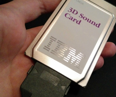
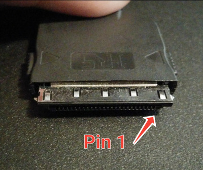
So I finally got my IBM 3D Sound card. But it has no dongle.
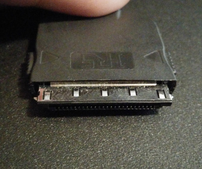
I'm 99% sure that it uses the standard Hirose (HRS) 25 pin connector.
Model ## NX30TA-25PAA + NX-25T-CV
connector.jpg
All measurements match at least. Here is original pdf with full details.

Filename
NX.pdf
File size
594.56 KiB
Downloads
95 downloads
File comment
HRS connectors
File license
Public domain

I'm about to receive the connectors, and will be able to confirm if they fit.
In the meanwhile I would like to ask if:
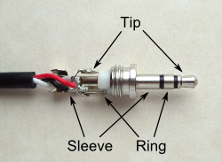
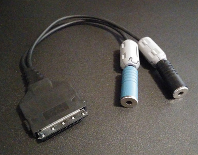
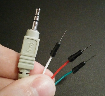
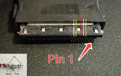
- anyone happen to have the pinout of the audio cable?
- or could anyone, who has the original cable, determine the 3 audio out pins with a tester?
3d-sound-card-IBM-dongle.jpg
Any help with this will be highly appreciated!!

PCMCIA Sound Cards chart
archive.org: PCMCIA software, manuals, drivers

Reply 1 of 14, by Kahenraz

User metadata
Rank l33t
Rank
l33t

I would be happy to help with this but I do not have an oscilloscope, which I think might be needed in this case to visualize the output by a fine-pitch probe.

I checked with both Digikey and Mouser. This part isn't normally stocked and has to be special ordered with an (unknown) minimum quantity. I submitted a request for a quote with Digikey but I would expect the minimum to be significant as they would have to setup and tool for it specifically.

https://www.mouser.com/ProductDetail/Hirose-C … TiBCdSCwA%3D%3D

Note that "availability" is "Non-Stocked, Call for Quote".

Reply 2 of 14, by Bondi

User metadata
Rank Oldbie
Rank
Oldbie

Oh, great! I believe all you need is a simple tester.
This set up should work just fine to find the right pins. And I believe it's non-destructive.
tester.jpg
I've ordered parts on www.digikey.com, they are on the way.

PCMCIA Sound Cards chart
archive.org: PCMCIA software, manuals, drivers

Reply 3 of 14, by Kahenraz

User metadata
Rank l33t
Rank
l33t

See attached images for reference.

The HRS logo appears "up" when the connector is inserted into the pcmcia card, aligned with the sticker that shows the product name and IBM logo.

The dongle has two stereo connectors, one blue, one black. I don't recall which one is the microphone and which is for audio out so I will refer to them by their color.

The pinout is as follows, counting from the rightmost pin as pin 1 when looking at the pins of the male connector with the HRS logo facing up.

Black female 3.5mm:
Pin 3 (ring)
Pin 4 (sleeve)
Pin 5 (tip)

Blue female 3.5mm:
Pin 7 (ring)
Pin 8 (sleeve)
Pin 9 (tip)

I'm using the terms sleeve, ring, and tip to eliminate any ambiguity as to how to wire this up.

Attachments

Last edited by Kahenraz on 2020-02-19, 21:30. Edited 1 time in total.

Reply 4 of 14, by Kahenraz

User metadata
Rank l33t
Rank
l33t

Adding this additional picture to make sure that which pin I'm referring to as "pin 1" is clear.

2020-02-19.jpg
Filename
2020-02-19.jpg
File size
640.62 KiB
Views
1441 views
File license
Public domain

Tested using a cable I made. Each part of the 3.5mm male end was checked for identification and continuity.

IMG_20200219_155801.jpg
Filename
IMG_20200219_155801.jpg
File size
380.9 KiB
Views
1439 views
File license
Public domain
Last edited by Kahenraz on 2020-02-19, 21:32. Edited 1 time in total.

Reply 8 of 14, by Bondi

User metadata
Rank Oldbie
Rank
Oldbie

Finally got the parts for the cable. The connector fits the card. Will assemble the cable later on today.
Here is what it all looks like.
IMG-2125.jpg
IMG-2126.jpg

PCMCIA Sound Cards chart
archive.org: PCMCIA software, manuals, drivers

Reply 11 of 14, by Bondi

User metadata
Rank Oldbie
Rank
Oldbie

And...it's working 😀
Kahenraz, thank you so much for yor help! Audio out was the first(black) jack, BTW.
Benedikt, yes, that's right, no soldeirng. Insulated wires work just fine, if they are thin enough. In my case I had to strip them.
IMG-2129.jpg

PCMCIA Sound Cards chart
archive.org: PCMCIA software, manuals, drivers

Reply 12 of 14, by Bondi

User metadata
Rank Oldbie
Rank
Oldbie

Just put this all together for ease of use.

pcmcia pinout.jpg
Filename
pcmcia pinout.jpg
File size
211.22 KiB
Views
1337 views
File license
Public domain

PCMCIA Sound Cards chart
archive.org: PCMCIA software, manuals, drivers

Reply 14 of 14, by Bondi

User metadata
Rank Oldbie
Rank
Oldbie
amang wrote on 2020-06-27, 01:50:

Thanks for showing us this information. How thick are your insulated wires? Also, what's the part near the end of the audio socket called?

I'm glad it was useful. My wires are 0.8 mm thick. That part is a ferrite bead https://en.wikipedia.org/wiki/Ferrite_bead

PCMCIA Sound Cards chart
archive.org: PCMCIA software, manuals, drivers