Reply 100 of 106, by sdz
Rank
Member
maxtherabbit wrote on 2023-02-18, 14:14:why on earth would you pay extra for ENIG on this?
It looks pretty.
maxtherabbit wrote on 2023-02-18, 14:14:why on earth would you pay extra for ENIG on this?
It looks pretty.
Wow, that looks freaking amazing!!
sdz wrote on 2023-02-18, 12:21:Took a little longer since I forgot to choose ENIG for the first PCBs and ordered again. Here's how they look: […]
Took a little longer since I forgot to choose ENIG for the first PCBs and ordered again. Here's how they look:
IMG_0127.jpg
IMG_0129.jpg
IMG_0131.jpg
IMG_0132.jpg
The logo looks way better in person than in the photos.
As a couple of suggestions:
-remove the 4 vias in the corners as they serve no purpose and just ruin the aesthetics a bit
-the traces should be less wide, especially L2 signal traces, as they are sandwiched between ground planes, the impedance will be very low, I'd just place all the signals on the bottom layer and have L3 as ground reference.
The corner vias are to tie the ground planes in the corners. Pointy areas can kinda act like antennas. It’s probably overkill for this pcb though. That much is true.
The pcb could probably also work on 2 layers (mess up the logo) or whatever arrangement you wanted if you wanted to move the rear signal layer to the middle that would also be fine, but I alternated them to isolate the signals from one one another as much as possible. Again, overkill.
Trace thickness, went as wide as possible, again, overkill. Tried to make it all overkill as nice as I could think to. There are many ways to do it as you can see in the thread.
Rather than change this one, since I am pretty happy with it, I will simply give full blessing to modify it as you like and make your own release that you will be more happy with. 😀
Btw, can you post pics of the solder colored ones you ordered initially also?
Looks great!
Nice work!
https://www.retrokits.de - blog, retro projects, hdd clicker, diy soundcards etc
https://www.retroianer.de - german retro computer board
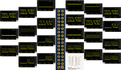
Sorry for reactivating this old post, but I need some advice! I'm rather amateurish when it comes to PCB design in general and I've never routed high-speed traces. I did some probing and followed the pinouts I found on this post. The two clock pins on the Voodoo SLI appear to be 80 and 40 MHz so I'm assuming that's the fastest signal among the DAC lines.
Based on the information here I made my own SLI bridge and it's been rather successful. Thanks for all the information people have contributed!
Simplified question... Based on the requirements for the Voodoo2 SLI bridge ribbon, how close can the traces get before I run into crosstalk issues on the high-speed lines? I'm looking to have the most space on a PCB SLI bridge for "other stuff" including possibly a microcontroller within the shortest path of the traces. This necessarily means I'd have to route them and possibly overlap the routes. In this case, I've chosen a 4 layer stack-up.( 1:GND 2:SIG/V 3:GND 4:SIG/V ) Another requirement is for a specific zone to be void of all copper and mask.
I'll include the first try and routing around the most space possible on a 60mm SLI bridge.
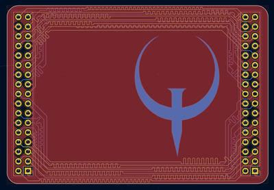
This is the test PCB files from Kicad 8. I routed 1/2 of the pins above and below the Quake logo and 1/2 again are routed on layers 2 and 4 so they're separated by a ground plane. This condenses the traces to about <7mm wide patch above and below on the PCB. I tried to offset and avoid routing over others on the adjacent layers and I also tried to tune the traces to equal lengths. There was no hard size limit to the outline and simply went with 69mm x 47mm around the two 34-pin headers. I'm tempted to try this and see if it works, but maybe someone can offer a recommendation or say why this might not work... Thx ahead of time and thx for all the info here!
It will work fine how you routed it, spacing is good and all traces have a reference plane.
Thx! That's what I was hoping for.
Off topic @sdz, that 4444SX card is a BEAST! Must have cost a fortune to make!
No problem!
Thanks! It did cost quite a bit, but totally worth it 😁