VOGONS


First post, by FormulaV8

User metadata
Rank Newbie
Rank
Newbie

Hello, hope everyone is doing well. I have an ECS N2U400-A Socket A motherboard with a bad flash. I can't get it to do a floppy check for bios recovery or anything.

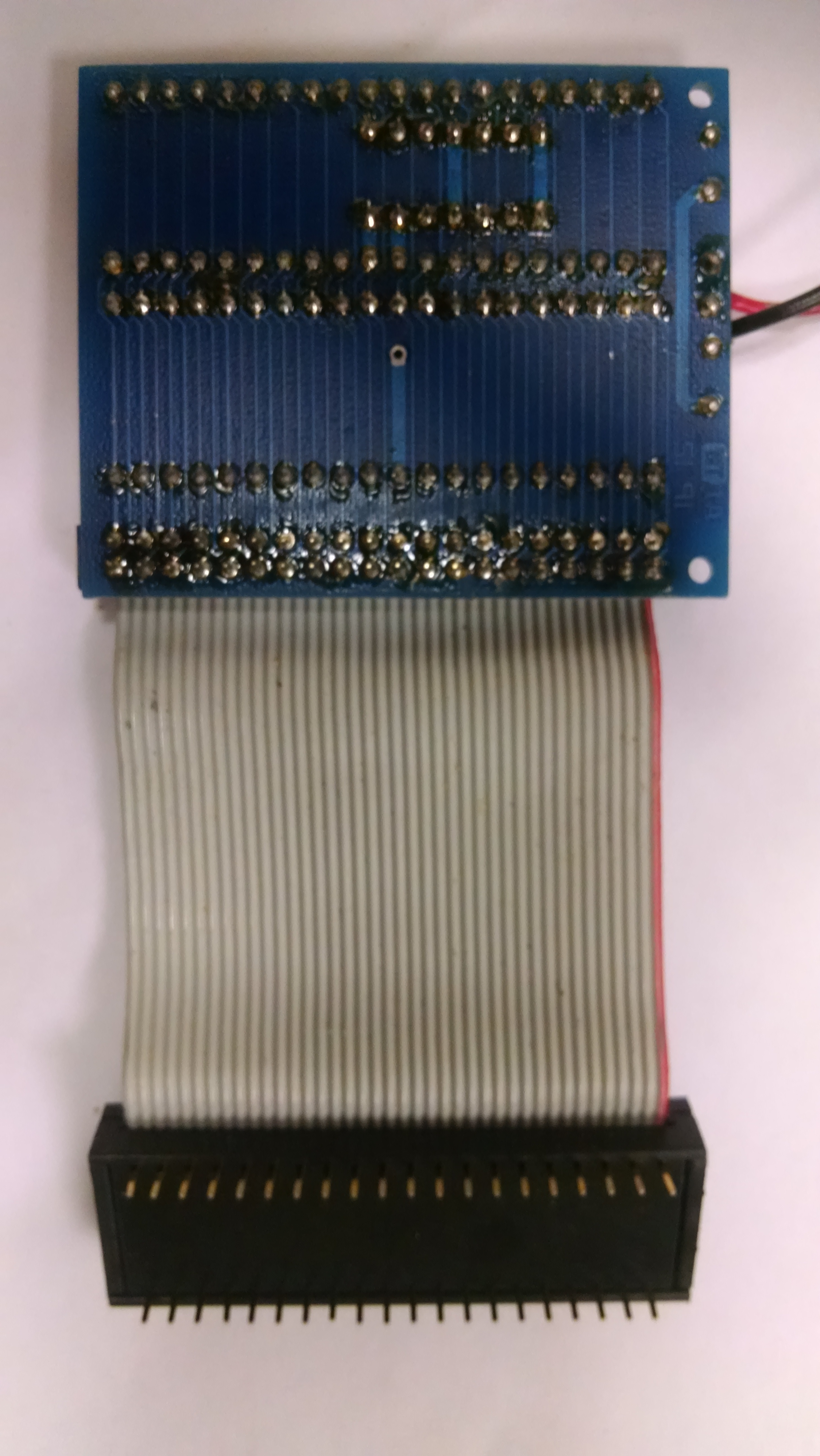
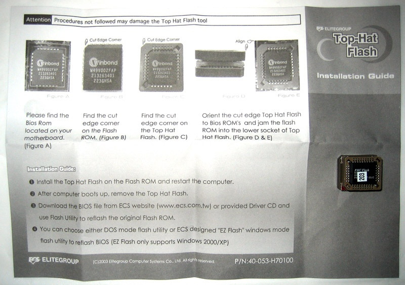
The Winbond W49V002AP bios chip is soldered so I can't hot flash. I have 2x different chip programmers but can't see any of my adaptors fitting the chip. I know there used to be a Tophat flash but I can't find one anythere.

The 2x programmers I have are: Ch341a with just a clip I believe. The other is: LAQIYA TL866Ⅱ Plus, and this is the kit that came with it: https://www.amazon.com/gp/product/B07CDD9PGT/ … 0?ie=UTF8&psc=1

If neither of these programmers or adapters I have will work, does anyone know the Adaptor I need to get for it to work?

Thanks for any help.

Jason

Reply 1 of 23, by Horun

User metadata
Rank l33t++
Rank
l33t++

From Google images the board Winbond W49V002AP bios has pins on 4 sides (32 Pin PLCC) you need a 32 pin PLCC to DIP 32 adapter, very common adapter for TL866.
My XGecu TL866 II Plus (xgecupro ebay seller) came with 13 adapters which included two different 32 PLCC to DIP adapters.

Hate posting a reply and then have to edit it because it made no sense 😁 First computer was an IBM 3270 workstation with CGA monitor. Stuff: https://archive.org/details/@horun

Reply 3 of 23, by Horun

User metadata
Rank l33t++
Rank
l33t++

You cannot connect the adapter to a soldered PLCC. They do make "clips" with short cable but have never seen one for the 4 sided PLCC, only for two sided smaller SOIC and TSOP types (and they are rare and very expensive !) .

Hate posting a reply and then have to edit it because it made no sense 😁 First computer was an IBM 3270 workstation with CGA monitor. Stuff: https://archive.org/details/@horun

Reply 4 of 23, by Sphere478

User metadata
Rank l33t++
Rank
l33t++

Unsolder the chip with hot air, order a socket, and an adapter for programmer. Then program and install in new socket

Sphere's PCB projects.
-
Sphere’s socket 5/7 cpu collection.
-
SUCCESSFUL K6-2+ to K6-3+ Full Cache Enable Mod
-
Tyan S1564S to S1564D single to dual processor conversion (also s1563 and s1562)

Reply 5 of 23, by darry

User metadata
Rank l33t++
Rank
l33t++
Horun wrote on 2022-06-19, 01:22:

You cannot connect the adapter to a soldered PLCC. They do make "clips" with short cable but have never seen one for the 4 sided PLCC, only for two sided smaller SOIC and TSOP types (and they are rare and very expensive !) .

And in at least some cases flashing, or even reading, a chip that is soldered into a circuit will not work due to, AFAIU, the circuit interacting with the externally programmer.

For example, the EEPROM chip that contains the PCI device ID on SB Live! and Audigy cards must be de-soldered before being read or re-programmed externally.

AFAICR, the EEPROM in some ( most, all ?) FC1307 based IDE to SD adapters is also like this .

Reply 6 of 23, by darry

User metadata
Rank l33t++
Rank
l33t++
Sphere478 wrote on 2022-06-19, 02:25:

Unsolder the chip with hot air, order a socket, and an adapter for programmer. Then program and install in new socket

This is the best solution .

Unfortunately, unsoldering/soldering surface mount components is not within everyone's reach .

Personally, I am just starting to be reasonably confident in my potential ability to handle through-hole components . I still need to get myself a hot air gun, a de-soldering pump and a large supply of Kapton tape, and then to practice on dead boards .

Reply 7 of 23, by Horun

User metadata
Rank l33t++
Rank
l33t++
darry wrote on 2022-06-19, 02:26:
And in at least some cases flashing, or even reading, a chip that is soldered into a circuit will not work due to, AFAIU, the ci […]
Show full quote
Horun wrote on 2022-06-19, 01:22:

You cannot connect the adapter to a soldered PLCC. They do make "clips" with short cable but have never seen one for the 4 sided PLCC, only for two sided smaller SOIC and TSOP types (and they are rare and very expensive !) .

And in at least some cases flashing, or even reading, a chip that is soldered into a circuit will not work due to, AFAIU, the circuit interacting with the externally programmer.

For example, the EEPROM chip that contains the PCI device ID on SB Live! and Audigy cards must be de-soldered before being read or re-programmed externally.

AFAICR, the EEPROM in some ( most, all ?) FC1307 based IDE to SD adapters is also like this .

Yep. The ones I have seen are specific to certain types of eeproms on specific boards. IIRC there are also some mother boards with special header that a specific cable connects to for external programming (think some Intel and/or IBM have them) but most boards do not have that ;p

Hate posting a reply and then have to edit it because it made no sense 😁 First computer was an IBM 3270 workstation with CGA monitor. Stuff: https://archive.org/details/@horun

Reply 8 of 23, by darry

User metadata
Rank l33t++
Rank
l33t++
Horun wrote on 2022-06-19, 03:58:
darry wrote on 2022-06-19, 02:26:
And in at least some cases flashing, or even reading, a chip that is soldered into a circuit will not work due to, AFAIU, the ci […]
Show full quote
Horun wrote on 2022-06-19, 01:22:

You cannot connect the adapter to a soldered PLCC. They do make "clips" with short cable but have never seen one for the 4 sided PLCC, only for two sided smaller SOIC and TSOP types (and they are rare and very expensive !) .

And in at least some cases flashing, or even reading, a chip that is soldered into a circuit will not work due to, AFAIU, the circuit interacting with the externally programmer.

For example, the EEPROM chip that contains the PCI device ID on SB Live! and Audigy cards must be de-soldered before being read or re-programmed externally.

AFAICR, the EEPROM in some ( most, all ?) FC1307 based IDE to SD adapters is also like this .

Yep. The ones I have seen are specific to certain types of eeproms on specific boards. IIRC there are also some mother boards with special header that a specific cable connects to for external programming (think some Intel and/or IBM have them) but most boards do not have that ;p

My old Asus P5K Deluxe WIFI/AP motherboard had such a header which came in quite handy following a bad flash while I was experimenting with converting it to socket 771, AFAICR . It was actually cheaper and faster to buy an old Compaq Deskpro for 20$ (plus 5$ worth wiring and passives) locally to flash the Asus' BIOS using the Compaq's parallel port than to buy a proper EEPROM programmer at the time . I no longer have the Asus P5K (it is still in active use by friends), but I still have the Compaq in storage .

Reply 9 of 23, by Horun

User metadata
Rank l33t++
Rank
l33t++

Hmm never knew a Asus board had it, thanks for the info ! And a early happy fathers day to you and all Vogon'ers that are dad's 😁

Hate posting a reply and then have to edit it because it made no sense 😁 First computer was an IBM 3270 workstation with CGA monitor. Stuff: https://archive.org/details/@horun

Reply 11 of 23, by FormulaV8

User metadata
Rank Newbie
Rank
Newbie
FormulaV8 wrote on 2022-06-19, 14:27:

Thanks for the info everyone. I will order the new adaptor. Thanks

Hello, I was wondering if there is an adaptor that is similar to the Tophat flash adaptor that ECS had available. You insert a good bios chip and place the adaptor on top of the soldered bios chip and boot from the bios chip in the adaptor and then flash the soldered chip.

I am just alittle worried about desoldering the bios chip as i've never done it before. In case I end up having to desolder it, what would be an easier way for someone who hasn't done it before? I have a heatgun that may be easy to do it with? Thanks

Jason

Reply 12 of 23, by Sphere478

User metadata
Rank l33t++
Rank
l33t++
FormulaV8 wrote on 2022-06-20, 21:57:
Hello, I was wondering if there is an adaptor that is similar to the Tophat flash adaptor that ECS had available. You insert a g […]
Show full quote
FormulaV8 wrote on 2022-06-19, 14:27:

Thanks for the info everyone. I will order the new adaptor. Thanks

Hello, I was wondering if there is an adaptor that is similar to the Tophat flash adaptor that ECS had available. You insert a good bios chip and place the adaptor on top of the soldered bios chip and boot from the bios chip in the adaptor and then flash the soldered chip.

I am just alittle worried about desoldering the bios chip as i've never done it before. In case I end up having to desolder it, what would be an easier way for someone who hasn't done it before? I have a heatgun that may be easy to do it with? Thanks

Jason

Where are you located? Pm me. Maybe I can help

Sphere's PCB projects.
-
Sphere’s socket 5/7 cpu collection.
-
SUCCESSFUL K6-2+ to K6-3+ Full Cache Enable Mod
-
Tyan S1564S to S1564D single to dual processor conversion (also s1563 and s1562)

Reply 13 of 23, by Horun

User metadata
Rank l33t++
Rank
l33t++

Yes it is possible to use the ECS Top Hat adapter if you can find one, you still need to program another flash chip with your proper BIOS and have it in the Top Hat.
So if you could find one you would need another Winbond W49V002AP that you program with your TL866. One thing I always wondered was how they work since Dual bios boards have a jumper to change between.
The Top Hat must be able to disable the on board BIOS or else it would run in parallel which surely would cause some major issues with diff codes being simultaneously delivered to the data bus 😀

added: Sphere478 you probably could build one, have seen your work in other topics here and it is top notch !

Hate posting a reply and then have to edit it because it made no sense 😁 First computer was an IBM 3270 workstation with CGA monitor. Stuff: https://archive.org/details/@horun

Reply 14 of 23, by Sphere478

User metadata
Rank l33t++
Rank
l33t++
Horun wrote on 2022-06-21, 01:09:
Yes it is possible to use the ECS Top Hat adapter if you can find one, you still need to program another flash chip with your pr […]
Show full quote

Yes it is possible to use the ECS Top Hat adapter if you can find one, you still need to program another flash chip with your proper BIOS and have it in the Top Hat.
So if you could find one you would need another Winbond W49V002AP that you program with your TL866. One thing I always wondered was how they work since Dual bios boards have a jumper to change between.
The Top Hat must be able to disable the on board BIOS or else it would run in parallel which surely would cause some major issues with diff codes being simultaneously delivered to the data bus 😀

added: Sphere478 you probably could build one, have seen your work in other topics here and it is top notch !

Thank you 😀

Yeah, if you wanna pull together a few datasheets and research it, I can punch out a pcb for you. Just tell me what it needs to do.

That is a particularly perplexing situation though. How one chip could assert dominance over another while in parallel. My guess is there may be a pin for telling the chip to be quiet that is only connected to the lower chip and not the upper. Maybe like a IDE master/slave kinda thing.

In any case, it’s kinda silly to go through this much effort when the tools you need to make such a device would also allow you to just fix the chip its self without said device.

Is this what you are talking about?

D1CC2BF0-3221-4918-8AB7-5811F567C7BA.jpeg
Filename
D1CC2BF0-3221-4918-8AB7-5811F567C7BA.jpeg
File size
23.21 KiB
Views
1756 views
File license
Public domain

In theory if that whole master slave thing works like I think it does, you could sinply leave it there if you wanted. Or do a hot flash with it. Boot the system, pull it, run the flash utility.

Edit: datasheet
https://html.alldatasheet.com/html-pdf/86965/ … /W49V002AP.html

Sphere's PCB projects.
-
Sphere’s socket 5/7 cpu collection.
-
SUCCESSFUL K6-2+ to K6-3+ Full Cache Enable Mod
-
Tyan S1564S to S1564D single to dual processor conversion (also s1563 and s1562)

Reply 15 of 23, by Sphere478

User metadata
Rank l33t++
Rank
l33t++

Did some looking into this:

I recalled how on some really old units they were able to switch to dual roms.

https://bigbookofamigahardware.com/bboah/medi … c8dd3b75a13.jpg

So I found this for amiga.

They don’t mention a particular rom model number so I just googled 40 pin rom

I found this data sheet:

https://www.digchip.com/datasheets/download_d … umber=MX23C4100

If I am counting the pins right those traces from the control IC look like they are going to the pins on the datasheet marked for CE for chip enable.

So it’s as I thought, there is a pin for enabling the master chip.

I see no such pin on the datasheet for OP’s chip unless I missed it.

So I suspect that this may not be an option for OP

Sphere's PCB projects.
-
Sphere’s socket 5/7 cpu collection.
-
SUCCESSFUL K6-2+ to K6-3+ Full Cache Enable Mod
-
Tyan S1564S to S1564D single to dual processor conversion (also s1563 and s1562)

Reply 16 of 23, by Horun

User metadata
Rank l33t++
Rank
l33t++

Yes I looked at that too, one of the docs from ECS shows exact same BIOS chip but could not figure out how the onboard would be disabled. Friends dual BIOS board has a jumper for A or B but the Top Hat has none.....
https://cdn.staticneo.com/neo_image/143929/ar … eme/tophat2.jpg (from https://www.neoseeker.com/Articles/Hardware/R … 1extreme/2.html )
and https://www.coreboot.org/Developer_Manual/Tools#BIOS_Savior says about Top Hat:
"The RST# pin is wired to OE# on the spare chip" works some how if they are correct,
need to read the datasheet with a clearer mind because that tells me to how enable the Spare but does not explain the shut off the on-board unless I am missing something 😀
Added: " By means of some 'obscure' cicuitry" and " Sadly, this simple technique does not seem to work with other boards right away. " Sigh ! 🤣
edited for proper content ;p

Hate posting a reply and then have to edit it because it made no sense 😁 First computer was an IBM 3270 workstation with CGA monitor. Stuff: https://archive.org/details/@horun

Reply 17 of 23, by Sphere478

User metadata
Rank l33t++
Rank
l33t++

Ah, sneaky! they named the pin OE instead of CE

Reset OperationThe #RESET input pin can be used in some application. When #RESET pin is at high state, the device is in normal operation mode. When #RESET pin is at low state, it will halt the device and all outputs will be at high impedance state. As the high state re-asserted to the #RESET pin, the device will return to read or standby mode, it depends on the control signals.

It may be that the OE pin is on the top chip and it is holding the lower one in reset?

So you may actually be able to turn this into a dual bios mod by adding a jumper.

Sphere's PCB projects.
-
Sphere’s socket 5/7 cpu collection.
-
SUCCESSFUL K6-2+ to K6-3+ Full Cache Enable Mod
-
Tyan S1564S to S1564D single to dual processor conversion (also s1563 and s1562)

Reply 18 of 23, by Sphere478

User metadata
Rank l33t++
Rank
l33t++

Okay,

tophat3.jpg
Filename
tophat3.jpg
File size
67.05 KiB
Views
1688 views
File license
Public domain
tophat2.jpg
Filename
tophat2.jpg
File size
14.72 KiB
Views
1688 views
File license
Public domain
ecskn1extreme_bios1.jpg
Filename
ecskn1extreme_bios1.jpg
File size
15.67 KiB
Views
1688 views
File license
Public domain

The images that I can find seem to show all of the traces going to the lower layer.

what happens there, we are left to ponder and research.

In the meantime, I finished the device. only thing left to do is to figure out the wire trick and incorporate it.

Schematic.png
Filename
Schematic.png
File size
64.15 KiB
Views
1688 views
File license
Public domain
Filename
Bios Saver Alpha 1.zip
File size
433.25 KiB
Downloads
43 downloads
File license
Public domain

Sphere's PCB projects.
-
Sphere’s socket 5/7 cpu collection.
-
SUCCESSFUL K6-2+ to K6-3+ Full Cache Enable Mod
-
Tyan S1564S to S1564D single to dual processor conversion (also s1563 and s1562)

Reply 19 of 23, by Horun

User metadata
Rank l33t++
Rank
l33t++
Sphere478 wrote on 2022-06-22, 03:48:
Ah, sneaky! they named the pin OE instead of CE […]
Show full quote

Ah, sneaky! they named the pin OE instead of CE

Reset OperationThe #RESET input pin can be used in some application. When #RESET pin is at high state, the device is in normal operation mode. When #RESET pin is at low state, it will halt the device and all outputs will be at high impedance state. As the high state re-asserted to the #RESET pin, the device will return to read or standby mode, it depends on the control signals.

It may be that the OE pin is on the top chip and it is holding the lower one in reset?

So you may actually be able to turn this into a dual bios mod by adding a jumper.

Yes was thinking that the Top Hat could thru a small resistor tie the onboard #OE (or #Reset to ground putting it in "halt" state and use the VSS thru small resistor to hold the Top Hat "re-asserted" to read mode).
My best guess is using the #OE pin. It may not even need a resistor but would think testing with a micro 100 ohm would be a safe test. The idea of adding a 3 pole jumper to select A or B (grounding to each OE) is very likely workable.
Would like to decode those lines on a ECS motherboard to see how they are implimented....my reading of the datasheet without sample circuit is confusing me as bothe OE and Reset seem to halt the read in some fashion....
From the SST49LF002A datasheet "Read The Read operation of the SST49LF00xA device is con-trolled by OE#. OE# is the output control and is used to gate data from the output pins. "
edit: fixed a boo-boo ;p

Hate posting a reply and then have to edit it because it made no sense 😁 First computer was an IBM 3270 workstation with CGA monitor. Stuff: https://archive.org/details/@horun