VOGONS


First post, by Jo22

User metadata
Rank l33t++
Rank
l33t++

Hello everyone,

While fixing my TNC, I did remember these tips from the internet for removing noise from the power supply.

"Mod for the PK-232 that helps eliminate RFI to your HF rig while trying to copy HF signals, eg. RTTY, CW, etc.

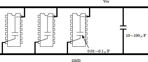
Place 1 MFD tantalium capacitors (Radio Shack) between pins 4 and 11 of the op amp chips U23, 26, 28, 30, 32, 34 to reduce the noise on the power buss to these chips. IT WORKS!!!
I STRONGLY urge all owners of the PK-232 to make this mod to your units. The noise figure was cut way down.

Thanks goes out to these hams for their efforts in cuttindown the noise in this otherwise noisy TNC."

Source: http://f4cqa.free.fr/modposte/pk232/pk232.htm

That's all fine so far, but I remember that it is even better to add two more caps: 100 Nanofarad(s) and 10 Nanofarad(s) .
In addition to the 1000 Nanofarad(s) (1 Microfarad)..

Now I wonder, since these values weren't mentioned by that operator back then - are there further values or filtering methods that I myself miss?

It's just for the sake of curiosity, doesn't need to be practical. 😄
- I'm not using switching-psus in my shack, of course.

Best regards,
Jo22

"Time, it seems, doesn't flow. For some it's fast, for some it's slow.
In what to one race is no time at all, another race can rise and fall..." - The Minstrel

//My video channel//

Reply 1 of 6, by Jo22

User metadata
Rank l33t++
Rank
l33t++

Quick update. Found an interesting page on a Toshiba site.

The recommended filter capacities for the ICs seem to be between 100 nF (0,1 µF) and 10 nF (0,01 µF),
whereas the power rail/bus is supported by a 10 µF to 100 µF condenser.

Anyway, maybe adding an extra 1000 nF (1 µF) to the ICs each shouldn't hurt.
Vintage ICs had a higher power draw, too, sometimes.

https://toshiba.semicon-storage.com/ap-en/sem … _common_06.html

logic_common_06_feature_1_en.png

"Time, it seems, doesn't flow. For some it's fast, for some it's slow.
In what to one race is no time at all, another race can rise and fall..." - The Minstrel

//My video channel//

Reply 2 of 6, by Jo22

User metadata
Rank l33t++
Rank
l33t++

Quick update. This one is also interesting..

https://www.infineon.com/dgdl/Infineon-AN1032 … s-v05_00-EN.pdf

It says that capacitors should be installed at the same board side as the IC.
If only that was so easy. Hm. Inside the spare room of a DIP/DIL socket, maybe, yes. 🙂

"Time, it seems, doesn't flow. For some it's fast, for some it's slow.
In what to one race is no time at all, another race can rise and fall..." - The Minstrel

//My video channel//

Reply 3 of 6, by Jo22

User metadata
Rank l33t++
Rank
l33t++

Quick update. For the sake of fairness, I'll also mention this funny article here. 😉


Low ESR Capacitors - Fact or Fiction ?

(archived version)

At least it does explain that ESR becomes less critical the "bigger" the cap.

"Time, it seems, doesn't flow. For some it's fast, for some it's slow.
In what to one race is no time at all, another race can rise and fall..." - The Minstrel

//My video channel//

Reply 4 of 6, by vstrakh

User metadata
Rank Member
Rank
Member
Jo22 wrote on 2022-03-26, 21:46:

That's all fine so far, but I remember that it is even better to add two more caps: 100 Nanofarad(s) and 10 Nanofarad(s) .
In addition to the 1000 Nanofarad(s) (1 Microfarad)..

Now I wonder, since these values weren't mentioned by that operator back then - are there further values or filtering methods that I myself miss?

Dave at EEVblog say the 100nF was the cheap "maxed out" capacity for a given physical size of the ceramic capacitor, so was a de-facto standard for bypassing.
Even smaller (physically) capacitors are needed for higher noise frequencies, and the smaller capacitance is just the consequence of the physical size decrease, it's not that it's the smaller capacity that was needed. The geometry/construction of capacitor defines the inductance that worsens the capacitor's ESR at higher frequency, so SMDs are the best option.

Jo22 wrote on 2022-03-26, 21:46:

- are there further values or filtering methods that I myself miss?

It's just for the sake of curiosity, doesn't need to be practical. 😄

Like winding the power cord on the ferrite ring to make a common mode choke? 😀

Reply 5 of 6, by Jo22

User metadata
Rank l33t++
Rank
l33t++

Thank you very much for the information! 😄👍

For choosing the right AC/RF filter capacitor minimum voltage,
I vaguely remember that the factor must be 1,41 for the DC input voltage.
Was somehow related to peek envelope something?

So for exampl, a digital IC running at 5V DC needs a decoupling capacitor, intended for filtering, (say bipolar, 100 nF) that can handle at least ~7V AC ?

But at the same time, a simple smoothing/stabilizing capacitor,
intended to prevent voltage spikes caused by the digital IC, (say single polarity, 1 µF) merely need to handle 5V DC ?

vstrakh wrote on 2022-10-27, 07:58:
Jo22 wrote on 2022-03-26, 21:46:

- are there further values or filtering methods that I myself miss?

It's just for the sake of curiosity, doesn't need to be practical. 😄

Like winding the power cord on the ferrite ring to make a common mode choke? 😀

Ah yes, I know them from my CB radio hobby!
I've also used ferrite clips to get rid of those sheet waves!
It greatly helped to silemce those awful switching PSU!
Also attached them to computer cables.. 🙂💙

"Time, it seems, doesn't flow. For some it's fast, for some it's slow.
In what to one race is no time at all, another race can rise and fall..." - The Minstrel

//My video channel//

Reply 6 of 6, by vstrakh

User metadata
Rank Member
Rank
Member
Jo22 wrote on 2022-10-27, 21:36:

I vaguely remember that the factor must be 1,41 for the DC input voltage.
Was somehow related to peek envelope something?

So for exampl, a digital IC running at 5V DC needs a decoupling capacitor, intended for filtering, (say bipolar, 100 nF) that can handle at least ~7V AC ?

The 1.4 coefficient though is likely related to the AC peak vs RMS values, with relation being square root of 2.
The 5v of filtered DC power needs 5v*sqrt(2) AC peak. Without the load (or "not enough" load) the voltage in capacitor will reach full AC peak value, so the cap has to be rated for that voltage too.

There are other kind of voltage derating, defined by the manufacturer and being mostly related to the physical properties of materials, aiming to lower the chances of failures in wide range of operational conditions. Manufacturer often publish recommendations on voltage/temperature derating for specific types of caps, the derating %% is very different between materials.

Another weirdness with SMD multilayer ceramic caps - the capacitance drops quite severely as the voltage is nearing the cap's rated limit. If the capacitance value is of importance, then proper derating should be applied when choosing the capacitor for this specific application.