VOGONS


[SOLVED] Keyboard + mouse connectors problem

Topic actions

Reply 40 of 88, by boby
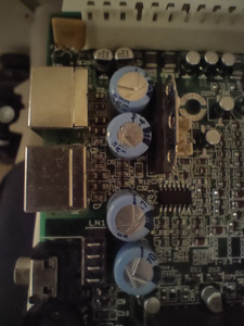
User metadata
Rank Member
Rank
Member
rasz_pl wrote on 2024-01-08, 15:53:
those capacitors look fine, no leakage, no corrosion looking closer at https://www.vogons.org/thumbs/52335_70daf02d3ca304935556 […]
Show full quote

those capacitors look fine, no leakage, no corrosion
looking closer at
IMG_3486.jpg
all this black woven stuff is laminate material burned into pure conductive carbon, but you measured resistance and reported 16Kohm so it might still somehow be fine

>Tried this today, but same result. Kb works, but reports error and stucks if any of the keys with LED is pressed.
>So connector is off the board and soldered just 4 wires.

did you solder those 4 wires to original pads or like I suggested power/ground from molex/motherboard power connector?
LED screwing with communication suggests keyboard is powered by parasitic power only - either power or ground is not connected
take a needle, plug it into pin 3 of the ps2 connector (ground), measure resistance between needle and ground on the motherboard

>DCC vs Data pin: ~ 16kOhm
>DCC vs. clock pin: no connection, multimeter show 1

VCC 😀 and Clock pin should show same resistance to VCC as Data pin. Some keyboards will work without one, some will not.

WELL, you were right. I tested solution where power + ground was taken from the original source. With those connected to PSU directly KB works without problems and no error on boot!
Thank you enormous much! 😀

So how should I proceed from here? Should I take power/ground for kb & mouse from power supply or somewhere else? From PSU it takes direct power, is that good idea?
Why original source is dropping voltage?

Reply 41 of 88, by rasz_pl

User metadata
Rank l33t
Rank
l33t

check original PS2 connector VCC/ground pads, or whats left of them, for resistance to AT power connector 5V/ground. I suspect you burned out copper from one of those holes.

https://github.com/raszpl/FIC-486-GAC-2-Cache-Module for AT&T Globalyst
https://github.com/raszpl/386RC-16 memory board
https://github.com/raszpl/440BX Reference Design adapted to Kicad
https://github.com/raszpl/Zenith_ZBIOS MFM-300 Monitor

Reply 42 of 88, by boby

User metadata
Rank Member
Rank
Member
rasz_pl wrote on 2024-01-08, 21:03:

check original PS2 connector VCC/ground pads, or whats left of them, for resistance to AT power connector 5V/ground. I suspect you burned out copper from one of those holes.

Well, ground hole is having brake in connection, so you need to lean the pin in order to have connection. But when I did the test without PSU, I took a working ground elsewhere but the kb still didn't work.
So ground hole is loose, but the problem is power line. I think. Or the ground has to be from specific point?
Old connector is in good shape 🙂

Reply 43 of 88, by rasz_pl

User metadata
Rank l33t
Rank
l33t

just for sanity check resistance of yellow element in this photo in upper left corner, I think Its marked FB1, afaik its a polyfuse - those normally do not permanently blow, but maybe yours did or you somehow damaged it mechanically while struggling with connectors
IMG20231228180452.jpg

https://github.com/raszpl/FIC-486-GAC-2-Cache-Module for AT&T Globalyst
https://github.com/raszpl/386RC-16 memory board
https://github.com/raszpl/440BX Reference Design adapted to Kicad
https://github.com/raszpl/Zenith_ZBIOS MFM-300 Monitor

Reply 44 of 88, by boby

User metadata
Rank Member
Rank
Member
rasz_pl wrote on 2024-01-09, 05:52:
just for sanity check resistance of yellow element in this photo in upper left corner, I think Its marked FB1, afaik its a polyf […]
Show full quote

just for sanity check resistance of yellow element in this photo in upper left corner, I think Its marked FB1, afaik its a polyfuse - those normally do not permanently blow, but maybe yours did or you somehow damaged it mechanically while struggling with connectors
IMG20231228180452.jpg

It is marked as F1 so I assume it is a fuse. Checked it before and it beeps, so should not be blown. Will check resistance as well.

Regarding my question from before. If I need to take 5V power or ground for my kb, where should I take it from? Directly from PSU?

Reply 45 of 88, by rasz_pl

User metadata
Rank l33t
Rank
l33t

Safest would be locating original break, easiest straight from under AT supply connector.

https://github.com/raszpl/FIC-486-GAC-2-Cache-Module for AT&T Globalyst
https://github.com/raszpl/386RC-16 memory board
https://github.com/raszpl/440BX Reference Design adapted to Kicad
https://github.com/raszpl/Zenith_ZBIOS MFM-300 Monitor

Reply 46 of 88, by boby

User metadata
Rank Member
Rank
Member
rasz_pl wrote on 2024-01-09, 13:19:

Safest would be locating original break, easiest straight from under AT supply connector.

Is it safe to go from under AT connector? Should I add some fuse, or something?

Reply 48 of 88, by weedeewee

User metadata
Rank l33t
Rank
l33t

boby,

Just an FYI.

https://theretroweb.com/motherboard/image/pl5 … c5166238295.jpg
While not very clear, it is possible, if you squint, to distinguish the different traces and to which pad they go, aside from one which I think is ground and likely connected to an inside or top groundplane.

Right to repair is fundamental. You own it, you're allowed to fix it.
How To Ask Questions The Smart Way
Do not ask Why !
https://www.vogonswiki.com/index.php/Serial_port

Reply 49 of 88, by boby

User metadata
Rank Member
Rank
Member
weedeewee wrote on 2024-01-09, 18:08:
boby, […]
Show full quote

boby,

Just an FYI.

https://theretroweb.com/motherboard/image/pl5 … c5166238295.jpg
While not very clear, it is possible, if you squint, to distinguish the different traces and to which pad they go, aside from one which I think is ground and likely connected to an inside or top groundplane.

Not sure that I understood you. Sorry, what do you mean?

Reply 50 of 88, by weedeewee

User metadata
Rank l33t
Rank
l33t
boby wrote on 2024-01-09, 20:04:
weedeewee wrote on 2024-01-09, 18:08:
boby, […]
Show full quote

boby,

Just an FYI.

https://theretroweb.com/motherboard/image/pl5 … c5166238295.jpg
While not very clear, it is possible, if you squint, to distinguish the different traces and to which pad they go, aside from one which I think is ground and likely connected to an inside or top groundplane.

Not sure that I understood you. Sorry, what do you mean?

I mean, you can look at the photo and compare it to how you soldered your ps2 connectors.

Right to repair is fundamental. You own it, you're allowed to fix it.
How To Ask Questions The Smart Way
Do not ask Why !
https://www.vogonswiki.com/index.php/Serial_port

Reply 51 of 88, by boby

User metadata
Rank Member
Rank
Member
weedeewee wrote on 2024-01-09, 21:29:
boby wrote on 2024-01-09, 20:04:
weedeewee wrote on 2024-01-09, 18:08:
boby, […]
Show full quote

boby,

Just an FYI.

https://theretroweb.com/motherboard/image/pl5 … c5166238295.jpg
While not very clear, it is possible, if you squint, to distinguish the different traces and to which pad they go, aside from one which I think is ground and likely connected to an inside or top groundplane.

Not sure that I understood you. Sorry, what do you mean?

I mean, you can look at the photo and compare it to how you soldered your ps2 connectors.

Yes, yes, I am using it as a reference.

But I Think I found the issue. On the image bellow there is a probe pointing to this component FB1, which I have no clue what it is, but the power trace from the kb, leads to it. However, when powered on and kb connected to original pins, this component shows 5V on the side where the probe is and 2.5V on the other side. So here is where voltage drops. What is this component and how to get a new one?

Reply 52 of 88, by weedeewee

User metadata
Rank l33t
Rank
l33t
boby wrote on 2024-01-09, 21:42:
weedeewee wrote on 2024-01-09, 21:29:
boby wrote on 2024-01-09, 20:04:

Not sure that I understood you. Sorry, what do you mean?

I mean, you can look at the photo and compare it to how you soldered your ps2 connectors.

Yes, yes, I am using it as a reference.

But I Think I found the issue. On the image bellow there is a probe pointing to this component FB1, which I have no clue what it is, but the power trace from the kb, leads to it. However, when powered on and kb connected to original pins, this component shows 5V on the side where the probe is and 2.5V on the other side. So here is where voltage drops. What is this component and how to get a new one?

Looks like an SMD component, an SMD coil. It tends to act as a cheapish fuse.
I wouldn't be surprised that it splits in two when you try to remove it.
though, No current idea about what values that coil might have.

Right to repair is fundamental. You own it, you're allowed to fix it.
How To Ask Questions The Smart Way
Do not ask Why !
https://www.vogonswiki.com/index.php/Serial_port

Reply 53 of 88, by DerBaum

User metadata
Rank Oldbie
Rank
Oldbie

FB is short for Ferrite Bead... wich is in fact like said from weedeewee really just a small coil wich should measure the same on both ends.
https://www.mouser.de/new/taiyo-yuden/taiyo-FBM-ferrite/

Last edited by DerBaum on 2024-01-09, 22:01. Edited 1 time in total.

FCKGW-RHQQ2

Reply 54 of 88, by boby

User metadata
Rank Member
Rank
Member

So what should I do?

Reply 55 of 88, by DerBaum

User metadata
Rank Oldbie
Rank
Oldbie
boby wrote on 2024-01-09, 22:00:

So what should I do?

Find out if something on the side with the lower voltage is dragging down the voltage sent over the bead.
That is done by checking if something is connected between the lower voltage side and ground.
,
if you are sure the side with the lower voltage of the bead is really connected to "nothing" and the voltage still drops... its probably broken...

FCKGW-RHQQ2

Reply 56 of 88, by weedeewee

User metadata
Rank l33t
Rank
l33t
boby wrote on 2024-01-09, 22:00:

So what should I do?

do a resistance measurement on that component. and replace the component if the resistance is higher than 1 ohm.

Right to repair is fundamental. You own it, you're allowed to fix it.
How To Ask Questions The Smart Way
Do not ask Why !
https://www.vogonswiki.com/index.php/Serial_port

Reply 57 of 88, by DerBaum

User metadata
Rank Oldbie
Rank
Oldbie
weedeewee wrote on 2024-01-09, 22:09:
boby wrote on 2024-01-09, 22:00:

So what should I do?

do a resistance measurement on that component. and replace the component if the resistance is higher than 1 ohm.

i suggested the voltage drop test because ferite beads can have a resistance from up to 2k ohm... this is why i linked the article on beads above.

I didnt know that too before.

FCKGW-RHQQ2

Reply 58 of 88, by weedeewee

User metadata
Rank l33t
Rank
l33t
DerBaum wrote on 2024-01-09, 22:12:
weedeewee wrote on 2024-01-09, 22:09:
boby wrote on 2024-01-09, 22:00:

So what should I do?

do a resistance measurement on that component. and replace the component if the resistance is higher than 1 ohm.

i suggested the voltage drop test because ferite beads can have a resistance from up to 2k ohm... this is why i linked the article on beads above.

I didnt know that too before.

The ferrite bead is in the voltage path that supplies power to the keyboard & mouse. the keyboard & mouse, according to google, should not draw more than 275mA.
Given that both like their voltage to be +5v +-%5%, the resistance of that component can be no more than 0.9ohm.

edit: it could be 1.8ohm if you go from 5.25 to 4.75, dropping .5 over the component, but meh.

Right to repair is fundamental. You own it, you're allowed to fix it.
How To Ask Questions The Smart Way
Do not ask Why !
https://www.vogonswiki.com/index.php/Serial_port

Reply 59 of 88, by DerBaum

User metadata
Rank Oldbie
Rank
Oldbie
weedeewee wrote on 2024-01-09, 22:20:
The ferrite bead is in the voltage path that supplies power to the keyboard & mouse. the keyboard & mouse, according to google, […]
Show full quote
DerBaum wrote on 2024-01-09, 22:12:
weedeewee wrote on 2024-01-09, 22:09:

do a resistance measurement on that component. and replace the component if the resistance is higher than 1 ohm.

i suggested the voltage drop test because ferite beads can have a resistance from up to 2k ohm... this is why i linked the article on beads above.

I didnt know that too before.

The ferrite bead is in the voltage path that supplies power to the keyboard & mouse. the keyboard & mouse, according to google, should not draw more than 275mA.
Given that both like their voltage to be +5v +-%5%, the resistance of that component can be no more than 0.9ohm.

edit: it could be 1.8ohm if you go from 5.25 to 4.75, dropping .5 over the component, but meh.

it measures probably a short (if its not broken). you are right.
It would be interesting anyway to see if there are internal shorts in the board or something like that.

FCKGW-RHQQ2