VOGONS


[SOLVED] Keyboard + mouse connectors problem

Topic actions

Reply 60 of 88, by weedeewee

User metadata
Rank l33t
Rank
l33t
DerBaum wrote on 2024-01-09, 22:37:
weedeewee wrote on 2024-01-09, 22:20:
The ferrite bead is in the voltage path that supplies power to the keyboard & mouse. the keyboard & mouse, according to google, […]
Show full quote
DerBaum wrote on 2024-01-09, 22:12:

i suggested the voltage drop test because ferite beads can have a resistance from up to 2k ohm... this is why i linked the article on beads above.

I didnt know that too before.

The ferrite bead is in the voltage path that supplies power to the keyboard & mouse. the keyboard & mouse, according to google, should not draw more than 275mA.
Given that both like their voltage to be +5v +-%5%, the resistance of that component can be no more than 0.9ohm.

edit: it could be 1.8ohm if you go from 5.25 to 4.75, dropping .5 over the component, but meh.

it measures probably a short (if its not broken). you are right.
It would be interesting anyway to see if there are internal shorts in the board or something like that.

true, though that only feeds the ps2 connectors

So

boby, did you measure the voltage drop on fb1 with the keyboard or mouse plugged in ?

Right to repair is fundamental. You own it, you're allowed to fix it.
How To Ask Questions The Smart Way
Do not ask Why !
https://www.vogonswiki.com/index.php/Serial_port

Reply 62 of 88, by boby

User metadata
Rank Member
Rank
Member
weedeewee wrote on 2024-01-09, 22:59:
true, though that only feeds the ps2 connectors […]
Show full quote
DerBaum wrote on 2024-01-09, 22:37:
weedeewee wrote on 2024-01-09, 22:20:

The ferrite bead is in the voltage path that supplies power to the keyboard & mouse. the keyboard & mouse, according to google, should not draw more than 275mA.
Given that both like their voltage to be +5v +-%5%, the resistance of that component can be no more than 0.9ohm.

edit: it could be 1.8ohm if you go from 5.25 to 4.75, dropping .5 over the component, but meh.

it measures probably a short (if its not broken). you are right.
It would be interesting anyway to see if there are internal shorts in the board or something like that.

true, though that only feeds the ps2 connectors

So

boby, did you measure the voltage drop on fb1 with the keyboard or mouse plugged in ?

Yes, kb was plugged in. I remeber from before that I had 5V on the Dcc pin on the connector if the kb is not connected. When I connect it, the voltage drops

Reply 63 of 88, by boby

User metadata
Rank Member
Rank
Member

I just noticed, that the side with dropping voltage of this FB1 component is also connected with those two capacitors (or what they are) next to it. This C1 mark.
Please have a good look at the photo I shared before

Reply 64 of 88, by weedeewee

User metadata
Rank l33t
Rank
l33t
boby wrote on 2024-01-09, 23:23:
weedeewee wrote on 2024-01-09, 22:09:
boby wrote on 2024-01-09, 22:00:

So what should I do?

do a resistance measurement on that component. and replace the component if the resistance is higher than 1 ohm.

It shows 10 kOhm (powered off, it that makes any difference)

Replace component.

Right to repair is fundamental. You own it, you're allowed to fix it.
How To Ask Questions The Smart Way
Do not ask Why !
https://www.vogonswiki.com/index.php/Serial_port

Reply 65 of 88, by rasz_pl

User metadata
Rank l33t
Rank
l33t
boby wrote on 2024-01-09, 21:42:

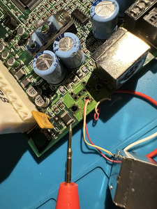
But I Think I found the issue. On the image bellow there is a probe pointing to this component FB1, which I have no clue what it is, but the power trace from the kb, leads to it. However, when powered on and kb connected to original pins, this component shows 5V on the side where the probe is and 2.5V on the other side. So here is where voltage drops. What is this component and how to get a new one?

IMG_3672.JPG

bingo! as DerBaum and weedeewee already explained its an inductor, its there to take care of any power spikes.
Simplified explanation: Inductors want to only conduct direct current and resist any voltage level changes. Capacitors on the other hand love conducting Alternating/jumping signals (AC) but will resist steady ones (DC). When you want smooth power you route supply thru serial inductor and put couple capacitors between positive voltage and ground for good measure. Inductor will do its best (like a car damper in the suspension) to only pass smooth steady voltage level, optional capacitors will take care of any eventual spikes by quickly conducting those to ground.
Why would and inductor want to block voltage swings? Lenz's Law! Here a cool demonstration https://www.youtube.com/watch?v=N7tIi71-AjA

weedeewee wrote on 2024-01-09, 21:49:

I wouldn't be surprised that it splits in two when you try to remove it.

I think this might be original defect of this motherboard, and its a design one! SMD inductor is too close to edge of PCB and keyboard/mouse connectors. Pulling on keyboard/mouse cable up/down will eventually crack it. Quite possible it was working intermittently for a long time after initial damage. I can imagine shenanigans like
- plugging only keyboard works fine because some keyboards will still somewhat function with degraded supply
- additionally plugging mouse either bends the crack more resulting in higher crack resistance and not enough power for both, or the mere mechanical action/weight of mouse cable breaks connection, unplug mouse and it starts to work again. User sees random behavior and goes crazy 😀

At least it wasnt an SMD capacitor in this unfortunate placement. Unlike breaking Inductors SMD Capacitors tend to go short, and it can get quite spectacular 😀 Story about capacitor failure caused by same mechanical reason - SMD component placed near PCB edge where user induces mechanical stress.

EEVblog #1036 - PSU Fire PCB Repair https://www.youtube.com/watch?v=VwdnGbI5ls8
EEVblog #1037 - Solving Ceramic Capacitor Cracking https://www.youtube.com/watch?app=desktop&v=QgKY5QWehME

boby this is really good news. Compaq let slip a design defect, somewhat fragile component sensitive to bending was plopped on board edge right next to connectors experiencing mechanical leverage every time user plugs/unplugs/moves cables. I bet this was your original failure, PS2 connectors were fine, but just plugging/unplugging something was causing intermittent power delivery. Fix is super easy, desolder FB1, replace it with a jumper (piece of wire). Inductor is non essential, its there in case someone doesnt read the instruction and plugs PS2 devices into a powered computer.

https://github.com/raszpl/FIC-486-GAC-2-Cache-Module for AT&T Globalyst
https://github.com/raszpl/386RC-16 memory board
https://github.com/raszpl/440BX Reference Design adapted to Kicad
https://github.com/raszpl/Zenith_ZBIOS MFM-300 Monitor

Reply 66 of 88, by boby

User metadata
Rank Member
Rank
Member

Thank you! I will try this solution.

Reply 67 of 88, by boby

User metadata
Rank Member
Rank
Member

So I manged to remove SMD inductor and applied piece of wire as a jumper. Voltage is now correct but the kb is not working this time at all. LEDs blink at the power on, but it is non responsive after. But that is not why I am writing this post.

I simply don't understand what am I doing wrong. When I was replacing this inductor with wire, I did it in like 2 mins and so easy, that I was surprised as well.
When I switched to solder the connector the nightmare started again.

I have rebuilt all the traces (and tested them), and then I applied solder mask + UV light to keep it in place and then I inserted the connector. Cleaned everything with IPA, applied flux and started to solder. However I did it, the soldering wire is sticking to my soldering iron instead of connector pins. I tried cleaning again, different flux, using bigger tip but all the time same problem. I am using 350 degrees (solder don't melt if lower). I put the soldering tip on the connector pin and then I put the soldering wire. It melts, but sticks to ironing tip instead of the connector pin. I am so frustrated at this moment that I am thinking to give up on everything, give away my PC for free and break my soldering ironing in pieces with a hammer and never to touch electronics again. Yes, I sound as a child even if I am 38 years old. But it drives me crazy. 🙁 🙁 🙁

Reply 68 of 88, by rasz_pl

User metadata
Rank l33t
Rank
l33t

Familiar feeling to anyone using shit tools 😀
As I already explained the reason behind your problems is modern multilayer PCB layout.
SMD Inductor is in series with power. Its two pads connect only to traces on PCB surface. Easy mode.
Connector is soldered in 4 out of 9 places to ground plane - a thick copper fill inside the PCB, invisible from the outside but stretching deep inside. For all intends and purposes its like soldering to a radiator. Your eyes see small pin, but your soldering iron is trying to heat up a flat piece of metal the size of quarter of the PCB. You need good technique, big TIP and soldering iron that will actually notice getting cold and deliver power on demand.

https://github.com/raszpl/FIC-486-GAC-2-Cache-Module for AT&T Globalyst
https://github.com/raszpl/386RC-16 memory board
https://github.com/raszpl/440BX Reference Design adapted to Kicad
https://github.com/raszpl/Zenith_ZBIOS MFM-300 Monitor

Reply 69 of 88, by boby

User metadata
Rank Member
Rank
Member
rasz_pl wrote on 2024-01-13, 19:19:
Familiar feeling to anyone using shit tools :) As I already explained the reason behind your problems is modern multilayer PCB l […]
Show full quote

Familiar feeling to anyone using shit tools 😀
As I already explained the reason behind your problems is modern multilayer PCB layout.
SMD Inductor is in series with power. Its two pads connect only to traces on PCB surface. Easy mode.
Connector is soldered in 4 out of 9 places to ground plane - a thick copper fill inside the PCB, invisible from the outside but stretching deep inside. For all intends and purposes its like soldering to a radiator. Your eyes see small pin, but your soldering iron is trying to heat up a flat piece of metal the size of quarter of the PCB. You need good technique, big TIP and soldering iron that will actually notice getting cold and deliver power on demand.

But then I should have no problem soldering non ground pins 🤔
Can you recommend any good soldering iron for simillar job, which is not too expensive?

Reply 70 of 88, by weedeewee

User metadata
Rank l33t
Rank
l33t

boby,
Will you do a little test with your soldering iron?
Set the temperature to 200°C, let it heat up, for lets say a minute, and touch your solder to it. It should melt if it's the tin/lead kind. though not very eagerly.
If there's no reaction, up the temperature by 20°C, let it heat up, and try again. Touch the solder to the tip

Let us know at what temperature you iron melts the solder.
Just the solder though, no pcb or components.

Right to repair is fundamental. You own it, you're allowed to fix it.
How To Ask Questions The Smart Way
Do not ask Why !
https://www.vogonswiki.com/index.php/Serial_port

Reply 71 of 88, by boby

User metadata
Rank Member
Rank
Member
weedeewee wrote on 2024-01-13, 20:08:
boby, Will you do a little test with your soldering iron? Set the temperature to 200°C, let it heat up, for lets say a minute […]
Show full quote

boby,
Will you do a little test with your soldering iron?
Set the temperature to 200°C, let it heat up, for lets say a minute, and touch your solder to it. It should melt if it's the tin/lead kind. though not very eagerly.
If there's no reaction, up the temperature by 20°C, let it heat up, and try again. Touch the solder to the tip

Let us know at what temperature you iron melts the solder.
Just the solder though, no pcb or components.

280 degress. I use 0.6 mm Lead free solder wire, 2.0% Flux

Reply 72 of 88, by boby

User metadata
Rank Member
Rank
Member

The fu*k, I have lead free solder but says 2.0% flux?!

Reply 73 of 88, by DerBaum

User metadata
Rank Oldbie
Rank
Oldbie
DerBaum wrote on 2024-01-01, 19:25:

Let me just mention that you should use leaded solder with flux core, if you are not already using it.
It makes life more easy.

let me mention that again...

FCKGW-RHQQ2

Reply 74 of 88, by weedeewee

User metadata
Rank l33t
Rank
l33t
boby wrote on 2024-01-13, 20:27:
weedeewee wrote on 2024-01-13, 20:08:
boby, Will you do a little test with your soldering iron? Set the temperature to 200°C, let it heat up, for lets say a minute […]
Show full quote

boby,
Will you do a little test with your soldering iron?
Set the temperature to 200°C, let it heat up, for lets say a minute, and touch your solder to it. It should melt if it's the tin/lead kind. though not very eagerly.
If there's no reaction, up the temperature by 20°C, let it heat up, and try again. Touch the solder to the tip

Let us know at what temperature you iron melts the solder.
Just the solder though, no pcb or components.

280 degress. I use 0.6 mm Lead free solder wire, 2.0% Flux

Which kind of lead free solder ? the alloy composition should be mentioned somewhere.

Right to repair is fundamental. You own it, you're allowed to fix it.
How To Ask Questions The Smart Way
Do not ask Why !
https://www.vogonswiki.com/index.php/Serial_port

Reply 75 of 88, by boby

User metadata
Rank Member
Rank
Member
DerBaum wrote on 2024-01-13, 20:37:
DerBaum wrote on 2024-01-01, 19:25:

Let me just mention that you should use leaded solder with flux core, if you are not already using it.
It makes life more easy.

let me mention that again...

Yes yes, my bad, I was sure it is the one with flux inside. At end there is a smoke 🙂

Reply 76 of 88, by boby

User metadata
Rank Member
Rank
Member
weedeewee wrote on 2024-01-13, 20:40:
boby wrote on 2024-01-13, 20:27:
weedeewee wrote on 2024-01-13, 20:08:
boby, Will you do a little test with your soldering iron? Set the temperature to 200°C, let it heat up, for lets say a minute […]
Show full quote

boby,
Will you do a little test with your soldering iron?
Set the temperature to 200°C, let it heat up, for lets say a minute, and touch your solder to it. It should melt if it's the tin/lead kind. though not very eagerly.
If there's no reaction, up the temperature by 20°C, let it heat up, and try again. Touch the solder to the tip

Let us know at what temperature you iron melts the solder.
Just the solder though, no pcb or components.

280 degress. I use 0.6 mm Lead free solder wire, 2.0% Flux

Which kind of lead free solder ? the alloy composition should be mentioned somewhere.

It doesn't say.

Reply 77 of 88, by boby

User metadata
Rank Member
Rank
Member

What about my solder tips. I use 2 on the very right:

Reply 78 of 88, by weedeewee

User metadata
Rank l33t
Rank
l33t
boby wrote on 2024-01-13, 20:50:
DerBaum wrote on 2024-01-13, 20:37:
DerBaum wrote on 2024-01-01, 19:25:

Let me just mention that you should use leaded solder with flux core, if you are not already using it.
It makes life more easy.

let me mention that again...

Yes yes, my bad, I was sure it is the one with flux inside. At end there is a smoke 🙂

Unfortunately most lead free solder has a higher melting temp.

Also, counting from the left, 2, 5 & 11 ,to me, seem better suited.
Also when soldering, place tip of iron on pad & leg of component to solder, start counting, 1 second, 2 3 4 5, add solder to the joint, 6 7 8 9 10, remove iron.

and
get better solder. That stuff you're using now, unmarked, the size isn't even indicated... It's a good way to get frustrated.

Right to repair is fundamental. You own it, you're allowed to fix it.
How To Ask Questions The Smart Way
Do not ask Why !
https://www.vogonswiki.com/index.php/Serial_port

Reply 79 of 88, by boby

User metadata
Rank Member
Rank
Member
weedeewee wrote on 2024-01-13, 21:06:
Unfortunately most lead free solder has a higher melting temp. […]
Show full quote
boby wrote on 2024-01-13, 20:50:
DerBaum wrote on 2024-01-13, 20:37:

let me mention that again...

Yes yes, my bad, I was sure it is the one with flux inside. At end there is a smoke 🙂

Unfortunately most lead free solder has a higher melting temp.

Also, counting from the left, 2, 5 & 11 ,to me, seem better suited.
Also when soldering, place tip of iron on pad & leg of component to solder, start counting, 1 second, 2 3 4 5, add solder to the joint, 6 7 8 9 10, remove iron.

and
get better solder. That stuff you're using now, unmarked, the size isn't even indicated... It's a good way to get frustrated.

So those with angled tip? 2, 5 & 11