VOGONS


First post, by analog_programmer

User metadata
Rank Oldbie
Rank
Oldbie

Hi, retro PC fellas.

The day, that my old trusty Chieftec CFT-650-14C PSU gave up, has come. Some of PSU's electrolytic capacitors are completely leaked and bulged (I wonder how this PSU was capable to power my daily-driver old Phenom II desktop in such condition) and I decided to fully recap it. But there's always a but...

I removed all the capacitors from PSU's PCBs and I don't know which of these are "regular" or low ESR caps. There are four types of capacitors excluding the mains filtering big one which is fine according to my cheapo "transistor meter". Here they are: Teapo SC, Samxon GF(M), Samxon RL(M) and Jun Fu HS.

I think I can easily find some new Samwha (Samsung's caps - not bad), Samxon (also not bad), Elite (I don't know nothing about these), Panasonic and Nichicon low ESR electrolytic caps and also some polymer type Kemet and X-Con (never heard about these) caps, but I don't know which of the original ones are low ESR caps if any. Any info about parameters of these Teapo SC, Samxon GF(M), Samxon RL(M), Jun Fu HS will be of use.

Thanks in advance!

from СМ630 to Ryzen gen. 3
engineer's five pennies: this world goes south since everything's run by financiers and economists
this isn't voice chat, yet some people, overusing online communications, "talk" and "hear voices"

Reply 1 of 17, by kingcake

User metadata
Rank Oldbie
Rank
Oldbie

Teapo SC Series Datasheet: https://jamicon.teapo.com/upload/Capacitor/Series/SC.pdf
Samxon RL Series Datasheet: https://www.paullinebarger.net/DS/Samxo ... Series.pdf
Jun Fu HS Series Datasheet: https://www.junfu.com.tw/english/01_pro/downl … 21465371196.pdf

Teapo caps are garbage. Kemet polymer caps are excellent, if appropriate.

Reply 2 of 17, by lti

User metadata
Rank Member
Rank
Member

Samxon GF: https://www.paullinebarger.net/DS/Samxo ... Series.pdf

Samxon GF series was known to be failure-prone, but the rest of their caps seem okay (unless the RL series caps also failed). X-Con is Samxon's brand for polymer caps.

Teapo had an arrangement with Yageo back when they failed the most often (and before merging with Jamicon), but I don't know whether Yageo was the actual manufacturer of Teapo caps. Yageo does make electrolytic caps today, so they might have been. Yageo now owns Kemet, which makes their caps a little questionable. (Was that confusing enough?)

Elite caps are strangely expensive from US distributors, and I haven't seen many of them in stuff I tried to repair. Out of the few I've seen, none failed, but there are lots of pictures of blown ones in TV and monitor power supplies on Badcaps.

Reply 3 of 17, by analog_programmer

User metadata
Rank Oldbie
Rank
Oldbie

Thanks for the links and the info, guys! Yeah, most of these Teapo SC caps are leaked and bulged, but this PSU run perfectly fine for almost 15 years without any problems (I rarely shut down the machine with this PSU as it bears the role of main storage space/file server in my home network and this is the first time I opened the PSU after its refusal to power up the system last morning - actually PSU kept starting without any load), so these are not terribly bad 😀 Samxon RLs seems OK, but some of GFs are leaky too. Jun Fu HS caps (never heard of these) are all OK as they're on the small controller PCB, but I'll replace them too as their name seems very untrusty to me.

I see that all of the original electrolytic caps are with high ripple current (assume low impedance/ESR), so I'll go with available low ESR substitutes.

I have no idea if polymer capacitors are appropriate as replacement for electrolytic caps.

P.S. Ok, the new Samxon caps I can get are also from bad GF series, what about Samwha instead?

Last edited by analog_programmer on 2024-03-11, 06:14. Edited 1 time in total.

from СМ630 to Ryzen gen. 3
engineer's five pennies: this world goes south since everything's run by financiers and economists
this isn't voice chat, yet some people, overusing online communications, "talk" and "hear voices"

Reply 4 of 17, by TheMobRules

User metadata
Rank Oldbie
Rank
Oldbie

Teapo SC and Samxon GF are low ESR, you can replace those with Nichicon UPW series or equivalent.

Samxon RL and Jun Fu HS are general purpose (note the max. ripple being specified at 120Hz instead of 100KHz in the datasheets), so anything 105C rated should work there. Do try and get some decent brand though.

I would not use polymers on an old-ish power supply, their ESR is so low that it could affect the feedback circuit resulting in an unstable output. Here's what Panasonic has to say about it:

Panasonic wrote:

For Cout to minimize the output ripple voltage, low ESR is important. Accordingly, the effectiveness of low ESR conductive polymer electrolytic capacitors shown above is highly evaluated.
However, because low ESR of Cout may cause the switching power supply output to be unstable and even oscillate in some cases, attention is required.

Source: https://industrial.panasonic.com/ww/ss/technical/lc4

Reply 5 of 17, by kingcake

User metadata
Rank Oldbie
Rank
Oldbie
TheMobRules wrote on 2024-03-11, 06:14:
Teapo SC and Samxon GF are low ESR, you can replace those with Nichicon UPW series or equivalent. […]
Show full quote

Teapo SC and Samxon GF are low ESR, you can replace those with Nichicon UPW series or equivalent.

Samxon RL and Jun Fu HS are general purpose (note the max. ripple being specified at 120Hz instead of 100KHz in the datasheets), so anything 105C rated should work there. Do try and get some decent brand though.

I would not use polymers on an old-ish power supply, their ESR is so low that it could affect the feedback circuit resulting in an unstable output. Here's what Panasonic has to say about it:

Panasonic wrote:

For Cout to minimize the output ripple voltage, low ESR is important. Accordingly, the effectiveness of low ESR conductive polymer electrolytic capacitors shown above is highly evaluated.
However, because low ESR of Cout may cause the switching power supply output to be unstable and even oscillate in some cases, attention is required.

Source: https://industrial.panasonic.com/ww/ss/technical/lc4

Yes. Power supplies often need a min ESR to remain stable. Don't go ultra low ESR if not required.

Reply 6 of 17, by analog_programmer

User metadata
Rank Oldbie
Rank
Oldbie
TheMobRules wrote on 2024-03-11, 06:14:
Teapo SC and Samxon GF are low ESR, you can replace those with Nichicon UPW series or equivalent. […]
Show full quote

Teapo SC and Samxon GF are low ESR, you can replace those with Nichicon UPW series or equivalent.

Samxon RL and Jun Fu HS are general purpose (note the max. ripple being specified at 120Hz instead of 100KHz in the datasheets), so anything 105C rated should work there. Do try and get some decent brand though.

I would not use polymers on an old-ish power supply, their ESR is so low that it could affect the feedback circuit resulting in an unstable output. Here's what Panasonic has to say about it:

Panasonic wrote:

For Cout to minimize the output ripple voltage, low ESR is important. Accordingly, the effectiveness of low ESR conductive polymer electrolytic capacitors shown above is highly evaluated.
However, because low ESR of Cout may cause the switching power supply output to be unstable and even oscillate in some cases, attention is required.

Source: https://industrial.panasonic.com/ww/ss/technical/lc4

Thank you for these details. In this case I will not do any experiments with polymer caps. The new Samxon low ESR caps I can get are also from not so good GF series, what about Samwha instead? I'll replace Junk-Fu with some descent brand all purpose/regular caps (those are with smaller capacity 1 uF/50 V, 10 uF/25 V and 100 uF/16 V on the small controller PCB), but will it be a big problem if I replace the three Samxon RL with low ESR caps with same capacity and rated voltage - they're the ones with the lowest capacity on the main PCB: one 100 uF/16 V and two 220 uF/25 V (the rest are low ESR Samxon GF 1000 to 2200 uF/6.5 to 16 V)?

P.S. Now I see that "high ripple current" doesn't always go with "low impedance/ESR".

kingcake wrote on 2024-03-11, 06:15:

Yes. Power supplies often need a min ESR to remain stable. Don't go ultra low ESR if not required.

Understood, I will not use any polymer caps as substitutes.

from СМ630 to Ryzen gen. 3
engineer's five pennies: this world goes south since everything's run by financiers and economists
this isn't voice chat, yet some people, overusing online communications, "talk" and "hear voices"

Reply 7 of 17, by TheMobRules

User metadata
Rank Oldbie
Rank
Oldbie
analog_programmer wrote on 2024-03-11, 06:22:

Thank you for these details. In this case I will not do any experiments with polymer caps. The new Samxon low ESR caps I can get are also from not so good GF series, what about Samwha instead? I'll replace Junk-Fu with some descent brand all purpose/regular caps (those are with smaller capacity 1 uF/50 V, 10 uF/25 V and 100 uF/16 V on the small controller PCB), but will it be a big problem if I replace the three Samxon RL with low ESR caps with same capacity and rated voltage - they're the ones with the lowest capacity on the main PCB: one 100 uF/16 V and two 220 uF/25 V (the rest are low ESR Samxon GF 1000 to 2200 uF/6.5 to 16 V)?

Yeah, you should be OK using low ESR caps for the smaller ones (I suspect the 100uF/16V and 220uF/25 are used on the output of the -5V/-12V lines, pretty much anything will work there)... as long as you avoid ultra-low ESR electrolytics (which are not even produced anymore) and polymers for the reasons mentioned above you should be safe.

For the low ESR caps (SC and GF in this case) just try to find replacements that match the ripple and impedance @ 100KHz from the datasheet in addition to capacitance/voltage. More ripple tolerance is OK, and it doesn't need to be a totally strict match with the impedance, just stay in the ballpark and you'll be fine, the design of these circuits usually allows for some leeway as long as you stay between certain minimum and maximum values.

Reply 8 of 17, by momaka

User metadata
Rank Member
Rank
Member

Try sticking only with good Japanese brands like Rubycon, Panasonic, Nichicon, and United Chemicon.
SamWha is -kind of- junky... about on par with Samxon GF: they'll probably last you a few good years in the PSU, if not more... but eventually, you will have to re-recap the PSU again. In contrast, quality Japanese caps will be a lifetime repair.
As for Elite... they are so-so too. I've seen them used a lot in LCD monitors, and depending on which series we are talking about, they can be anywhere from very decent to not very good. Also depends if they have been abused with heat. The ones that weren't do OK. But again, if better quality caps are available to you, I'd go with those. The price difference should be negligible.
As for Jun Fu... Junk Fu is putting it nicely. I'm not a fan of this brand.

Here are some series that should work with your PSU from the above Japanese brands:
Rubycon: YXJ, YXH, YXM, PX (general purpose series), ZLQ*, ZL*
Panasonic: FC, FK, FR*, FM*, FS*
Nichicon: PW, PS, PM, PJ, HE, HD, HW*, HV*
United Chemicon: LXZ, LXY, LXV, KY, KYB, KZE, KZH*, KZM*

* : I've used some of these in PSUs before, but their ESR may be a bit too low for some PSUs.

Just follow what TheMobRules mentioned about matching the replacements. Indeed most PSUs tend to be quite flexible in what they can take, so it's not critical to match ESR or ripple current exactly. +/- 30 to 50% for the ESR is fine. Ripple current - higher than the original would be better... but in a pinch, lower RC from a high-quality Japanese cap manufacturer will usually do fine too. And as far as capacity and voltage ratings go: anywhere you see 6.3V caps, you can safely use 10V caps and vice versa. For capacity, going a notch up or down is usually not a problem either... though it's preferable to go up if the right size is not offered - e.g. putting a 1200 uF cap in place of a 1000 uF cap. Actually, even 1.5x higher capacitance won't hurt (if anything, higher capacitance is better... within reasonable limits, of course.)

In regards to the big cap(s) inside the PSU: does it have 2x 200V caps or one (or more) 400V/420V/450V caps. The former is typically accompanied by a voltage-selector switch and means the PSU does not have an APFC circuit. The latter means your PSU does have APFC. This is important to note, because APFC tends to stress the primary caps a lot more than non- or PPFC PSUs. So if the primary cap(s) is/are not a Japanese brand from the ones mentioned above (or Hitachi), you may want to replace it too. Just note that this/these large 400V/420V/450V caps will be rather expensive. My general rule is: if the PSU will be seeing a lot of use at high load and if the original cap was only rated for 400V (and especially if it's not a Japanese brand), then it's better to replace it - preferably with a cap rated for 420V or 450V. The primary cap doesn't have to be low ESR... and you will see that you probably won't find it in the above series. For this one, it just needs to be rated for 105C and as high ripple current as possible... and make sure that it physically fits inside your PSU too.
Last edited by momaka on 2024-03-11, 08:39. Edited 1 time in total.

Reply 9 of 17, by analog_programmer

User metadata
Rank Oldbie
Rank
Oldbie
TheMobRules wrote on 2024-03-11, 07:42:

Yeah, you should be OK using low ESR caps for the smaller ones (I suspect the 100uF/16V and 220uF/25 are used on the output of the -5V/-12V lines, pretty much anything will work there)... as long as you avoid ultra-low ESR electrolytics (which are not even produced anymore) and polymers for the reasons mentioned above you should be safe.

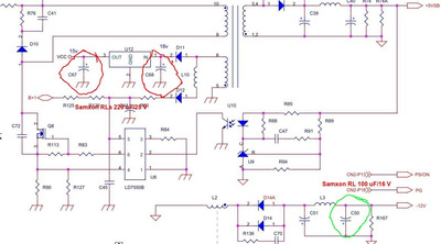
Unfortunately I can't find any circuit diagrams for this Chieftec PSU series. There's no -5 V line in this PSU, but there is -12 V and I think the only Samxon RL 100 uF/16 V is on the output of the -12 V line (have to check it with the multimeter for sure) and the other two Samxon RLs 220 uF/25 V are connected to one of the smallest transistors (I'm just guessing that it's a transistor) in the middle of the main PCB (I can not see exactly what is this transistor-like three-pin element because of the heatsinks shapes) - maybe they're related to +5 V stand-by voltage.

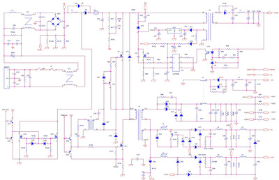
P.S. Ok, I found one circuit diagram for similar model CFT-650-14CS PSU here: https://drive.google.com/file/d/1AvUjao7uFNPY … 8wLJ9UX1PM/view

These are the three questionable all-purpose Samxon RLs, that I wonder if there will be a problem to be replaced by low ESR/impedance caps:

questionable_caps.jpg
Filename
questionable_caps.jpg
File size
81.19 KiB
Views
412 views
File license
Public domain
TheMobRules wrote on 2024-03-11, 07:42:

For the low ESR caps (SC and GF in this case) just try to find replacements that match the ripple and impedance @ 100KHz from the datasheet in addition to capacitance/voltage. More ripple tolerance is OK, and it doesn't need to be a totally strict match with the impedance, just stay in the ballpark and you'll be fine, the design of these circuits usually allows for some leeway as long as you stay between certain minimum and maximum values.

In worst case I'll go with Samxon GFs. The original ones lasted almost a decade and a half, so they're not so bad and seems better than Teapo SC. But first I'll check those Samwha low ESR - there's no info which series on the store's site. I think the Panasonic and Nichicon caps might be fake because of their listed low price.

momaka wrote on 2024-03-11, 08:30:
Try sticking only with good Japanese brands like Rubycon, Panasonic, Nichicon, and United Chemicon. SamWha is -kind of- junky... […]
Show full quote

Try sticking only with good Japanese brands like Rubycon, Panasonic, Nichicon, and United Chemicon.
SamWha is -kind of- junky... about on par with Samxon GF: they'll probably last you a few good years in the PSU, if not more... but eventually, you will have to re-recap the PSU again. In contrast, quality Japanese caps will be a lifetime repair.
As for Elite... they are so-so too. I've seen them used a lot in LCD monitors, and depending on which series we are talking about, they can be anywhere from very decent to not very good. Also depends if they have been abused with heat. The ones that weren't do OK. But again, if better quality caps are available to you, I'd go with those. The price difference should be negligible.
As for Jun Fu... Junk Fu is putting it nicely. I'm not a fan of this brand.

Here are some series that should work with your PSU from the above Japanese brands:
Rubycon: YXJ, YXH, YXM, PX (general purpose series), ZLQ*, ZL*
Panasonic: FC, FK, FR*, FM*, FS*
Nichicon: PW, PS, PM, PJ, HE, HD, HW*, HV*
United Chemicon: LXZ, LXY, LXV, KY, KYB, KZE, KZH*, KZM*

* : I've used some of these in PSUs before, but their ESR may be a bit too low for some PSUs.

Just follow what TheMobRules mentioned about matching the replacements. Indeed most PSUs tend to be quite flexible in what they can take, so it's not critical to match ESR or ripple current exactly. +/- 30 to 50% for the ESR is fine. Ripple current - higher than the original would be better... but in a pinch, lower RC from a high-quality Japanese cap manufacturer will usually do fine too. And as far as capacity and voltage ratings go: anywhere you see 6.3V caps, you can safely use 10V caps and vice versa. For capacity, going a notch up or down is usually not a problem either... though it's preferable to go up if the right size is not offered - e.g. putting a 1200 uF cap in place of a 1000 uF cap. Actually, even 1.5x higher capacitance won't hurt (if anything, higher capacitance is better... within reasonable limits, of course.)

In regards to the big cap(s) inside the PSU: does it have 2x 200V caps or one (or more) 400V/420V/450V caps. The former is typically accompanied by a voltage-selector switch and means the PSU does not have an APFC circuit. The latter means your PSU does have APFC. This is important to note, because APFC tends to stress the primary caps a lot more than non- or PPFC PSUs. So if the primary cap(s) is/are not a Japanese brand from the ones mentioned above (or Hitachi), you may want to replace it too. Just note that this/these large 400V/420V/450V caps will be rather expensive. My general rule is: if the PSU will be seeing a lot of use at high load and if the original cap was only rated for 400V (and especially if it's not a Japanese brand), then it's better to replace it - preferably with a cap rated for 420V or 450V. The primary cap doesn't have to be low ESR... and you will see that you probably won't find it in the above series. For this one, it just needs to be rated for 105C and as high ripple current as possible... and make sure that it physically fits inside your PSU too.

Thank you very much for all the detailed information! I've just sent you a PM, you'll see why 😉

The PSU is with Active PFC and one big mains filter capacitor Nippon ChemiCon SMQ 390 uF/400 V/85 C. I can't find any suitable replacement for this one due to its dimensions (nearby heatsinks and some transformers/chokes will interfere if I try to install slightly higher or wider capacitor), but the original one seems to be healthy enough and from a respected brand.

from СМ630 to Ryzen gen. 3
engineer's five pennies: this world goes south since everything's run by financiers and economists
this isn't voice chat, yet some people, overusing online communications, "talk" and "hear voices"

Reply 10 of 17, by analog_programmer

User metadata
Rank Oldbie
Rank
Oldbie

Finally I replaced all the electrolytic capacitors except mains filter capacitor 390 uF/400 V and one very little capacitor which is 0.33 uF. Tested the power supply without any load and it starts, gives all the +12 V, +5 V, +3.3 V, -12 V etc. lines, except the "power good" signal (grey wire), which I think must be +5 V.

Is this normal for ATX PSU without load?

This is the only diagram that I can find which is for models 14CS and mine is 14C. Unfortunately I can't see any PWM or control circuits here:

CFT-600~850-14CS.jpg
Filename
CFT-600~850-14CS.jpg
File size
275.17 KiB
Views
288 views
File license
Public domain

P.S. I found another discussion for 14C model on badcaps forum, but the problem there is with bad +5 V line. There are no circuit diagrams, but a couple of pictures of the control PCB.

from СМ630 to Ryzen gen. 3
engineer's five pennies: this world goes south since everything's run by financiers and economists
this isn't voice chat, yet some people, overusing online communications, "talk" and "hear voices"

Reply 11 of 17, by analog_programmer

User metadata
Rank Oldbie
Rank
Oldbie

Ok, as usually I'm asking and later I get answers by myself. So this "power good" +5 V signal is not related to motherboard's voltages, but formed internally by PSU's controller (if all the other voltages are presented as within the specs to the controller's chip ant there's no triggered protection).

I triple checked everything with the voltages of the PSU. After I switch on mains power the +5 VSB (stand by voltage - purple wire) is present and +5.07 V. After shorting the Power-On (green wire) to ground (black wire) the PSU turns on, its fan (12 V) starts spinning and the voltages for all lines are present and correct: +3.3 V (orange wires) = 3.36 V; +5 V (red wires) = 5.06 V; +12 V (yellow wires) = 11.94 V and -12 V (blue wire) = -11.94 V, but the +5 V PWR Good (grey wire) is missing.

And I think I have a problem with the little controller PCB for which I can't find any circuit diagrams:

Pictures taken from the badcaps forum, control PCB in my PSU is slightly different, maybe different revision

fetch?id=1906812
fetch?id=1906811

On my controller board I've replaced all the electrolytic capacitors with brand new ones, but probably there's something wrong with some of the other SMD components.

So, I'll definitely have to buy some brand new 650+ W ATX PSU, but now I'm thinking, what if I cut the grey wire and connect it to +5V red wire at 24-pin ATX connector? Will this "dirty hack" make the PSU usable at least for old hardware test bench PSU?

Last edited by analog_programmer on 2024-05-11, 06:36. Edited 1 time in total.

from СМ630 to Ryzen gen. 3
engineer's five pennies: this world goes south since everything's run by financiers and economists
this isn't voice chat, yet some people, overusing online communications, "talk" and "hear voices"

Reply 12 of 17, by analog_programmer

User metadata
Rank Oldbie
Rank
Oldbie

The "power good" signal to +5 V line dirty hack totally worked. Now I officially have a "100% chinese quality" ATX PSU of a respected brand. I hope the new Samxon GF caps will hold up well in +5 V lines at least for a couple of years. And for my surprise even in shi*ipedia this "power good" mod is stated:

"Cheaper and/or lower quality power supplies do not follow the ATX specification of a separate monitoring circuit; they instead wire the power good output to one of the 5 V lines. This means the processor will never reset given bad power unless the 5 V line drops low enough to turn off the trigger, which could be too low for proper operation."

Now I'm looking for brand new Seasonic PSU... I hope this brand keeps its good quality with the more recent models.

from СМ630 to Ryzen gen. 3
engineer's five pennies: this world goes south since everything's run by financiers and economists
this isn't voice chat, yet some people, overusing online communications, "talk" and "hear voices"

Reply 13 of 17, by darry

User metadata
Rank l33t++
Rank
l33t++
analog_programmer wrote on 2024-05-09, 09:14:

The "power good" signal to +5 V line dirty hack totally worked. Now I officially have a "100% chinese quality" ATX PSU of a respected brand. I hope the new Samxon GF caps will hold up well in +5 V lines at least for a couple of years. And for my surprise even in shi*ipedia this "power good" mod is stated:

"Cheaper and/or lower quality power supplies do not follow the ATX specification of a separate monitoring circuit; they instead wire the power good output to one of the 5 V lines. This means the processor will never reset given bad power unless the 5 V line drops low enough to turn off the trigger, which could be too low for proper operation."

Now I'm looking for brand new Seasonic PSU... I hope this brand keeps its good quality with the more recent models.

Maybe I'm talking nonsense here, but a monitoring circuit seems like it would be modular or interchangeable in this kind of scenario, if all it does is make sure all output voltages are in range and set PG low or high accordingly. Alternatively, at least setting PG assertion on a delay to give time for regulation to kick in would help avoid potential startup issues .

Reply 14 of 17, by analog_programmer

User metadata
Rank Oldbie
Rank
Oldbie
darry wrote on 2024-05-09, 10:49:

Maybe I'm talking nonsense here, but a monitoring circuit seems like it would be modular or interchangeable in this kind of scenario, if all it does is make sure all output voltages are in range and set PG low or high accordingly. Alternatively, at least setting PG assertion on a delay to give time for regulation to kick in would help avoid potential startup issues .

Well, even if I have some basic knowledge of electronics, can do small DIY PCB projects with one or two layers by given diagrams and sometimes I can successfully repair damaged electronic equipment, I'm not an electronics engineer and I can't design such electronic circuits. The small controller board also "measures" temperature inside the PSU housing and regulates the fan's speed in relation to this temperature, at least this part still works fine.

After the time I've lost in searching and replacing almost all of the electrolytic capacitors in this PSU, I'm very disappointed that the power supply is actually no longer working as expected due to a more serious problem. Without any schematic of the small controller board that forms the "power good" signal, I haven't any idea how it works, hence I can't trace a possible problem with this missing signal while there are all correct output voltages. The dumbest, simplest and easiest thing to pull off that came to my electrician's mind was to replace the "power good" signal with voltage from +5 v line, which value is already perfect from a specs standpoint (as the voltages of the other output power lines +12 V, +3.3 V and -12 V are also perfectly fine).

The PSU now works once plugged with a motherboard, though it's not up for constant use as it was before it failed.

I'm currently choosing a brand new ATX power supply, but it's a bit difficult task for me as I haven't had to do anything like that since I bought this one.

from СМ630 to Ryzen gen. 3
engineer's five pennies: this world goes south since everything's run by financiers and economists
this isn't voice chat, yet some people, overusing online communications, "talk" and "hear voices"

Reply 15 of 17, by analog_programmer

User metadata
Rank Oldbie
Rank
Oldbie

Another idea came to my mind. If I take a controller chip with a well documented circuit from another PSU (I have a couple of quite old working power supplies with lower power - up to 400 W), I can make an additional small PCB to be wired-in and which will be responsible only for monitoring the voltages of the output lines and to form the missing "power good" signal. But that would take some more time, and again I have no guarantee that it would end up with the desired result.

P.S. In my stash with old/spare electronic pars I found remains of PCB from PSU based on (AT)2005B controller chip. The chip is still soldered to the board, but I will need competent help on diagram for the small additional DIY PCB which will form the missing PG-signal while monitoring the output power lines voltages of the PSU.

Last edited by analog_programmer on 2024-05-09, 12:29. Edited 1 time in total.

from СМ630 to Ryzen gen. 3
engineer's five pennies: this world goes south since everything's run by financiers and economists
this isn't voice chat, yet some people, overusing online communications, "talk" and "hear voices"

Reply 16 of 17, by darry

User metadata
Rank l33t++
Rank
l33t++
analog_programmer wrote on 2024-05-09, 11:53:

Another idea came to my mind. If I take a controller chip with a well documented circuit from another PSU (I have a couple of quite old working power supplies with lower power - up to 400 W), I can make an additional small PCB to be wired-in and which will be responsible only for monitoring the voltages of the output lines and to form the missing "power good" signal. But that would take some more time, and again I have no guarantee that it would end up with the desired result.

P.S. In my stash with old/spare electronic pars I found remains of PCB from PSU based on (AT)2005B controller chip. The chip is still soldered to the board.

That was what I was thinking about when I mentioned "modular or interchangeable".

That being said, and on further thought, maybe there is a valid reason for that monitor circuit to not assert PG. Maybe it's detecting an issue with regulation, ripple, whatever else (I don't know how sophisticated these things are) that you may have not accounted for in your testing/measurements.

I am not an electrical engineer (at most maybe I would be qualified to play one in a TV show 😉 ), so I am just throwing ideas around, without full knowledge of what is safe or even sane, just to be clear. TBH, a new PSU seems like it might be more time and cost effective. I would not trust this one without at least some kind of monitoring working to safeguard against regulation silently going out if spec and/or, possibly OCP not kicking in when required (no idea if the monitoring circuit plays any role in triggering something on overcurrent events).

Reply 17 of 17, by analog_programmer

User metadata
Rank Oldbie
Rank
Oldbie
darry wrote on 2024-05-09, 12:29:

That was what I was thinking about when I mentioned "modular or interchangeable".

That being said, and on further thought, maybe there is a valid reason for that monitor circuit to not assert PG. Maybe it's detecting an issue with regulation, ripple, whatever else (I don't know how sophisticated these things are) that you may have not accounted for in your testing/measurements.

I am not an electrical engineer (at most maybe I would be qualified to play one in a TV show 😉 ), so I am just throwing ideas around, without full knowledge of what is safe or even sane, just to be clear. TBH, a new PSU seems like it might be more time and cost effective. I would not trust this one without at least some kind of monitoring working to safeguard against regulation silently going out if spec and/or, possibly OCP not kicking in when required (no idea if the monitoring circuit plays any role in triggering something on overcurrent events).

I'm sorry, darry, I misunderstood what you've exactly meant because of the word "interchangeable". I thought you're supposing to reverse engineer the original small PCB with the controller, but it is crowded with SMD elements and this is a task far beyond my competence 😀

As for the output ripple currents... This PSU worked fine until it suddenly failed with no signs of any problems, as it turned out later (when I opened it for the first time) that some of its electrolytic capacitors (which I replaced with brand new ones - Samxon GT and GF series for low ESR, and some Panasionic caps for regular ones) were bulged, leaked and with very degraded parameters compared to the marked values. I've replaced almost all of the electrolytic caps in this PSU (except two, which I can't find as a values, but still are measured good and within specs) with their original capacitance values and where it was possible with an order of magnitude up in voltage, so I think there will be no problems from that kind (too much ripple etc.). And on the other hand, some new (added by me) auxiliary DIY-board will again monitor the output voltage parameters to form the missing PG-signal from the original control PCB.

Now I'm thinking that this power supply actually stopped working because of a control PBC's SMD element failure and that's why it still doesn't work as expected (PG-signal is missing) after my cap's repair job.

analog_programmer wrote on 2024-03-11, 05:06:

this is the first time I opened the PSU after its refusal to power up the system last morning - actually PSU kept starting without any load

This was situation before any repair attempts. "Without load" means detached from the motherboard or any other devices and shorted green (power on) to black (ground) wires. The voltages without load was pretty much off specs, but it was able to start without load (detached from the mobo) and I thought - "uhh, It just failed because of all the leaky caps and no longer can bare any load".

The actual problem (beyond several leaked caps) was and still is because of the missing PG-signal from its freakin' small control board, everything else now is perfectly fine. If there really was still a problem with the output voltages, the power supply would have no way to start at all. It just loses the "power good" signal somewhere on the small control PCB and obviously no motherboard can start without it. And I can't trace this problem without any diagram for the PSU's small control board.

from СМ630 to Ryzen gen. 3
engineer's five pennies: this world goes south since everything's run by financiers and economists
this isn't voice chat, yet some people, overusing online communications, "talk" and "hear voices"