Update on the "Backwards PC104+ Adaptor Card"
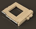
Good news and not so good news (for me anyway)...😋 And, if you're reading this and maybe want to try one, feel free to DM. However!!!! As you can see, this card is special and will not fully work in a genuine PISA/PCISA backplane. At least not the PCI function, as these backplanes are hardwired for IDESL# and INT#. This card is truly made for my Backwards Backplane. The power and ISA passthrough should. Meaning the ATX power connector on the card itself can pass power back to the backplane, and I've tested this on my IEI PCISA-compatible backplane. Oh, and most importantly, there is no slot bracket yet! Still looking into that one!
The attachment Backwards_PC104+_1.jpg is no longer available
The attachment Backwards_PC104+_2.jpg is no longer available
The attachment Backwards_PC104+_3.jpg is no longer available
I haven't tested every part, but the V1.0 board seems to be functional! The PC104 module can draw power from the PCISA slot or its onboard 20-pin ATX power connector. I still need to test the USB and Ethernet passthrough. I found a few mistakes in the PCM-3353 datasheet! The pinout order doesn't match the real pinout order on the physical board on some ports. 😬 Glad I double checked with a meter.
I hit a snag on first power-up. I was happy to see it powered up, meaning I routed it correctly. However, I got no ISA function! I mean zero! It took a few hours of troubleshooting and probing to see if all the PC104 ISA pins had continuity. Everything looked good, so I moved to check the signal on the scope. The rise and fall times all looked good. So, why wouldn't it see any ISA cards, including my ESS sound chip built into my backplane?
Upon probing, the ISA (MEMCS16) and (IOCS16) stayed HIGH all the time, even during boot or using something like UNISOUND to poke the sound cards. Both of my recently acquired PCM-3353 modules behaved the same way, so I was left assuming a signal or routing issue. Or even my termination, possibly interfering with the PC104 ISA bus. The BIOS on these cards has all the usual options, except that the resource allocation menu is lacking a few key things. Specifically, the ability to reserve DMA channels.
These PCM-3353 use an AMD Geode LX800. This is the clue, and during my search, I ran into how these AMD boards support the legacy IO. The companion chip AMD Geode CS5536 is the SouthBridge chip that "emulates" the ISA bus, or uses some other bridge IC that may not fully support legacy ISA! 🤦♂️🤦♂️ I didn't dig into the datasheet for this chip, but I did find another whitepaper that mentions something important.
---------------------
Issue:
PC/104 (ISA) expansion cards may exhibit problems or not work on some AMD Geode-based
CPU boards.
Background:
A number of VersaLogic SBCs use AMD Geode™ processors; namely, the GX 500 and LX 800
processors. The architecture of these chipsets does not include a PC/104 (ISA) interface. So
VersaLogic implemented a PLD that functions as an LPC-to-ISA bridge to accommodate the
use of ISA devices with these products.
Because the Low Pin Count (LPC) bus is an 8-signal interface, certain limitations apply to ISA
transfers. Memory reads and writes are limited to eight bits and DMA transfers are not
supported. Early revisions of the EPIC-2 (Gecko) and EPM-5 (Puma) also limited I/O transfers
to eight bits, but current versions support 16-bit transfers.
The LPC-to-ISA bridge used on VersaLogic Geode-based SBCs has the following
characteristics:
The memory range addressable by the bridge is C8000h to DBFFFh.
Generally, the I/O range supported is 0x100 to 0x3FF (see the SBC's reference manual
for exclusions).
Subtractive decoding is used to route traffic from the PCI bus to the LPC bus; however,
the LPC-to-ISA bridge operates in a positive decode mode.
The bridge typically supports a limited number of interrupts (see reference manual).
The bridge does not support:
o DMA
o zero wait state cycles
o memory refresh cycles
o bus master mode
o 16-bit memory transfers
Recommendations:
Given the architecture of Geode processors and the VersaLogic LPC-to-ISA bridge, a PC/104
(ISA) board will work on Geode-based SBCs provided the PC/104 board:
Requires only 8-bit memory transfers.
Does not require an interrupt other than those supported by the board (see reference
manual).
Does not require zero wait states.
Is not a bus master.
Does not use DMA.
---------------------
While this is for VersaLogic systems, the PCM modules may have the same or a similar architecture choice. If that's the case, there is no 16-bit ISA compatibility (even though the 16-bit extension connector is there!), and NO DMA support for ISA! This means no ISA sound cards! 🤦♂️🤦♂️ And, since I don't have any 8-bit ISA cards to test with, I left with the conclusion that my PCB routing is most likely correct, and an older PC104 board would work fine.
So far, the PCI function seems to work, and my PCI MAPPER cards indeed work as expected by emulating the IDSEL# and INT# hard-wired into the PCM module. Here's it working with a PCI graphics card.
The attachment Backwards_PC104+_4.jpg is no longer available
This is my first PCB using a beveled edge. I'm pleased with JLCPCB's work on this!
The attachment Backwards_PC104+_5.jpg is no longer available