Reply 31220 of 31477, by giantenemycat

- Rank
- Member
giantenemycat wrote on 2026-04-20, 01:14:MattRocks wrote on 2026-04-19, 06:30:My understanding is that we don't actually forget anything. Instead, what happens is certain memories become hard to access due […]
giantenemycat wrote on 2026-04-19, 04:04:I previously thought this was the only photo that "shows" my old family PC, which I've been on a years long quest to identify. […]
I previously thought this was the only photo that "shows" my old family PC, which I've been on a years long quest to identify.
But I had a feeling there was one big piece of evidence left. Went back through the photos today, and only noticed this in an index because I had a flashlight on it. Can't find the actual photo - looked through every single pack of photos for the negative at least, and it WAS in the very last pack with a completely unrelated set of photos.
I will get the negative digitised but not too much hope tbh. I can make out the index photo slightly better in person but it's a fumbled photo with poor lighting. Hopefully when blown up it'll show at least enough detail to make out if it's the model I think it is.
My understanding is that we don't actually forget anything. Instead, what happens is certain memories become hard to access due to bandwidth limitations.
And, we don't index or recall our memories in chronological order. Instead, we recall them by associations (smells, motions, emotions, temperature, heart rate, etc.)
So if you model how you completely felt when you were fixing your PC, and relive that complete set of associations, it's possible you might recall technical specifications you once knew.
But beware - when you recall memories, you also write new memories of recalling memories (recursion) and so un-recalled detail can be buried even further! Given that sensitivity, you might not benefit from a half-arsed practice run.
This is, imho, the entire thesis of therapy in a single post because if you think about it.. a person is the sum of their memories, and the way a person experiences anything is really just an effect of how they remember experiencing something else..
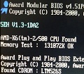
I don't trust my memories tbh. In the lifetime of that PC I was 6-12, and all I knew about PCs was that they had the Pentiums - Pentium this, Pentium that. In fact I remember telling people I had a Pentium II, but a printed Windows resource summary report I found a couple years ago indicates it was actually just a Pentium (MMX). So why was I so sure it was a PII?
I only think I know what PC it was because of that report, thanks to the BIOS revision and date listed. And some elements of the design do ring a bell, while some others kinda don't. So could be a red herring. I just need enough detail from that potato photo after processing the negative to tell if it's this specific AST Bravo LC/MS 51xx/52xx series chassis design. If it's not, then RIP.
Got the dodgy negative done professionally. It was indeed an AST Bravo MS/LC (probably LC) 51xx/52xx from the 1997 430TX series! Now I can just about make out the sticker above the W95 one is the plain blue "Intel Pentium" sticker, not MMX. So that narrows it down LC 5166 or 5200. No way to tell if the CPU was upgraded by my dad's friend before he sold it to him though. Probably not?
It was definitely a choice to have the left speaker underneath, next to the printer. Much like the bright green painted walls were also...interesting. And of course I've got my stack of Sold Out Software games at the bottom.
Anyone think they can figure out what monitor that is?
1999 Family PC: AST Bravo LC(?) 5166(?)/430TX(✔)/Pentium 166(?)/32MB(?) SDRAM/Virge DX\GX(✔)/ALS120(✔) - [OSR2 -> ME]
2006 Family PC: Generic Shuttle HOT-675/450MHz PIII/256MB SDRAM/Radeon 9200\9250/ST310240A 10.24GB - [XP SP2]