Mike_ wrote on 2026-04-29, 16:31:
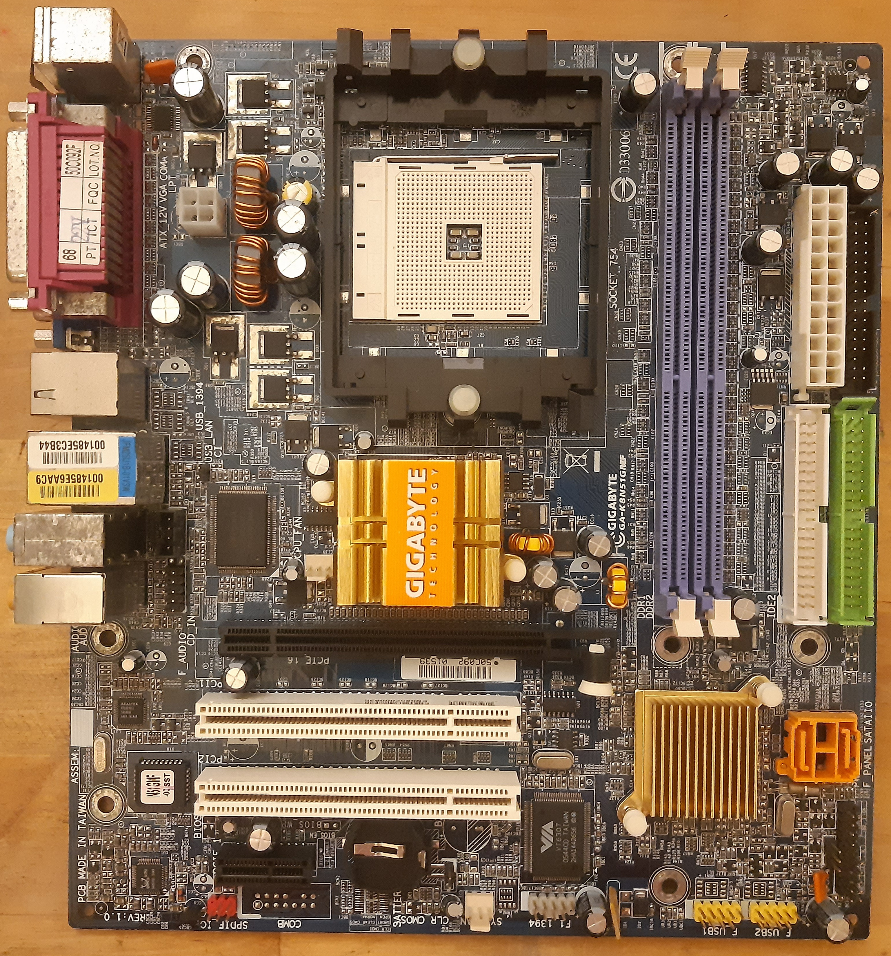
So I was checking the board with a multimeter, and it appears that capacitors TC6 and TC7 are simply filtering caps for 5V rail. But TC6 is a 1200µF 6,3V cap while TC7 is 330µF 25V... I wonder what's the point here? It's an odd choice to put caps like that in parallel.
TC6 is not an original cap, while TC7 is. However, based on this post it appears that the board originally had a similar cap in place so it's not a matter of somebody having used random caps in the recapping process.
Re: Bought these (retro) hardware today
Probably it was a cost-saving measure at the production floor.
My guess would be Gigabyte intended those cap spots (TC6, TC7, TC8, and TC9) to all be filled up with cheaper 25V 330 uF caps. Then someone on the production floor saw the design and probably figured there's a further opportunity to save more on costs by removing a few more caps from the BOM... until someone looked at this decision over and suddenly realized that only two 330 uF caps at spots TC6 and TC7 perhaps ain't going to cut it for the noise filtering. So instead of populating all of those cap spots again, perhaps they found it would be just cheaper to use one larger capacity cap at spot TC6 while still leaving TC7 with the original 330 uF cap. So they did that and called it done. (I know there is a lot of speculation here, but stories/decisions like this aren't actually uncommon.)
Worth noting here is that while all of these capacitor spots (TC6, 7, 8, and 9) appear to be in parallel (and on the 5V rail), they aren't actually so when it comes to high frequency AC noise filtering. If you look a little closer, toroidal inductor L14 is doing some separation there. To me, it appears that TC7 and TC8 are in parallel
"after" L14 and TC6 and TC9 are in parallel "before" L14. What I mean by this is that the "before" set should be connected with traces directly to the 5V pins on the ATX connector. The "after" group is also connected to the 5V rail on the PSU, but only after inductor L14. So what this arrangement does is it creates an C-L-C type filter (i.e. capacitor-inductor-capacitor filter.) Such filter is effective at filtering high frequency noise going back into the PSU and on the rest of the 5V rail going elsewhere to the motherboard.
IME, it's important that the "after" cap filter is done with proper low-ESR caps, since that is also technically the supply to the CPU VRM's upper MOSFETs.
So if this was my motherboard, I'd probably use 1200-2200 uF very low ESR caps in both spots, just to be consistent (or just 330-470 uF caps if going with polymers.) And no need to go with 25V -rated caps either (at least not if you used good low ESR caps.)
As for the rest of the 25V 330 uF Choyo caps on the board...
Except for the one between the PCI slots (which is likely filtering either a 3.3v or 5V rail from the PSU going into the PCI slots), the rest appear to be connected to linear regulators. In particular, the one in the upper-right corner by the RAM is probably for the RAM V_dd rail (i.e. 3.3V for SDRAM). Meanwhile, the 4 below the Northbridge are probably for either the Northbridge Vcc supply or the AGP slot communication voltage (3.3V or 1.5V switcheable for these "universal"/4x boards) - likely two before the linear regulator and two after it.
The 5th Choyo to the left of the RAM slots is probably also for the RAM V_dd, but not 100% sure.
PD2JK wrote on 2026-04-26, 15:58:
If the system runs stable, leave them be if you don't have any testing equipment available. But inspect them once in a while.
+1
For people who don't have the means to easily remove/replace caps (e.g. a good soldering iron and skills to use it comfortably on a motherboard) or test equipment to test them (cap meter), then this is probably indeed the more sound strategy to follow.
Otherwise, I'd pull at least one or two of these Choyo's and check their condition. If their ESR is "OK" and their capacitance is well within the 20% tolerance (more particularly, not getting close to the upper end of +20%), then they might be just fine to leave as is.
Shponglefan wrote on 2026-04-26, 16:16:
No reason to replace them if they look fine and everything is working.
Maybe.
I've had caps that appeared fine externally and the motherboard they were in was also working fine. But I pulled a few to check their condition, and they were actually starting to fail with abnormally high capacitance, which is indicative of the electrolyte inside the capacitor reacting with the foil plates and breaking it down. When that happens, it's just a matter of time before the capacitor becomes too failed and things stop working.
That said, I don't always pull capacitors to check them. If they are from a known good Japanese brand and not from a series that is known to be affected by issues (e.g. United Chemicon KZG, Sanyo WF, Nichicon HM and HN from 2001-2004, and etc.), then I leave them alone. If they are anything else, I use my knowledge/experience about how often I have seen that particular brand and series failed before to decide if I should remove any for a test.
andrea wrote on 2026-04-26, 19:50:
I also populated the unstuffed capacitors for the CPU VRM.
I tend to do that as well.
It's good insurance that you will have even better filtering.
Also, sometimes I do this when I'm too lazy to do a proper recap on a motherboard I don't care as much about. In such case, adding a few known good/reliable caps in the unpopulated empty spots that are in parallel basically allows the good caps to "hold over" the board even if the other original parallel caps fail.
Mike_ wrote on 2026-04-27, 16:14:
Why bother recycling capacitors when you can buy new ones for just a couple of euros? That sounds like a lot of effort for saving not much.
It's all relative to each person's situation.
Here, for a few euro, I can typically get a whole motherboard for scrap from the flea market or the metal recycling centers with all kinds of caps on it (and I usually do when they have good quality capacitors on them are cheap enough - e.g. under 1-2 Euro per board). This does two things for me: it guarantees I have a variety of motherboard-grade capacitors in stock and it IS much cheaper. With online retailers, some of the bigger caps can cost almost 1 euro per cap (which can add up fast if you need a lot of them.) In contrast, if I have a whole motherboard full of these, it brings the repair costs down considerably. Also, when buying stuff online, not only do I have to wait for the shipping, but I also have to walk all the way to the post office to collect it (and often pay either VAT or customs tax... or both.)
So yes, reusing caps can indeed be much more cost-effective. But again, it all depends on where you live an what you have available near you.
As for the effort part - it takes me maybe 10-20 seconds to remove a cap from a board, another 10 to pop it in my cap tester... and from there, it's ready to go back to use if it's good. In other words, it's hardly that much effort if you have all of the equipment to do it and at the ready.