VOGONS


First post, by Wampa

User metadata
Rank Newbie
Rank
Newbie

Hi everyone! I'm having a no-POST issue with the same board ASUS PCI/I-P5MP3 Rev. 2.4 and a Pentium 60 (with the FDIV bug).

Here is the current situation:

Symptom: The board doesn't turn on, no beeps from the speaker, and the CPU stays completely cold.

Power Supply: I'm using a modern ATX PSU with an ATX-to-AT adapter (P8/P9 connectors are correctly oriented with the black wires in the middle). When I flip the switch, the PSU fan spins regularly. I noticed that both ATX power supplies I have are missing the white -5V wire on the 20-pin connector (the pin slot is empty).

Test Bench Config: Board on the bench with only the CPU, one 72-pin SIMM RAM stick in slot 0, a Matrox Millennium PCI graphics card, and the PC speaker connected.

Troubleshooting done: I tried booting without RAM and without the GPU, but the behavior doesn't change (no beeps and cold CPU). I checked the jumper settings for the BIOS type selection (EPROM / Flash 5V/12V) and set it to 5V. I also tried the reset test by shorting the front panel header, but the CPU stays completely cold.

Does anyone know if this specific board strictly requires the -5V rail to POST, or if the cold CPU issue could be caused by a dead RTC/Dallas chip or a corrupted BIOS? Also, does anyone know the exact jumper settings to set the clock to 60MHz on this specific revision? Thanks a lot!
Reply 1 of 13, by rasz_pl

User metadata
Rank l33t
Rank
l33t

you can ignore -5V, not needed for boot
cold 5V cpu is weird tho, it should be getting 5V right away and at least getting warm even if held in reset?
do you have a multimeter?

https://github.com/raszpl/sigrok-disk FM/MFM/RLL decoder
https://github.com/raszpl/FIC-486-GAC-2-Cache-Module (AT&T Globalyst)
https://github.com/raszpl/386RC-16 ram board
https://github.com/raszpl/Zenith_ZBIOS Zenith Z-386 MFM-300 ZBIOS disassembly

Reply 2 of 13, by Wampa

User metadata
Rank Newbie
Rank
Newbie
rasz_pl wrote on 2026-07-12, 15:27:

you can ignore -5V, not needed for boot
cold 5V cpu is weird tho, it should be getting 5V right away and at least getting warm even if held in reset?
do you have a multimeter?

Yes, I have a multimeter, but I'm not very experienced with it. You'd need to tell me step-by-step what to check and how to do it... thanks.

Reply 3 of 13, by rasz_pl

User metadata
Rank l33t
Rank
l33t

just for sanity lets measure CPU supply, no idea how cpu could not be getting power, but hey you say its cold so who knows:
Multimeter in Voltage mode range <10V.
remove everything from motherboard, no cards no ram no cpu, just psu connected
put a steel needle in any of the Vcc holes in CPU socket, pinout on page 6 https://theretroweb.com/misc/documentation/24 … 22046088602.pdf for example C1
stick black multimeter probe into molex connector (the one for hard drives) middle pins (ones going to black wires)
red probe on the needle
turn on PSU and read the voltage, should be 5V

if that passes
connect a switch to Reset header, or have screwdriver in third hand to short it
needle in L18
multimeter in voltage mode
power on
press/short Reset while looking at multimeter to see if reading changes from 0 to ~5V and back to 0 after letting reset go

if that also happens then hmm it might be the case of one of those motherboards that act dead if Dallas RTC battery is dead. I dont know how to check it externally, afaik its encapsulated shut in plastic so you would have to pull one out from another motherboard or drill into this one _gently_ to get to battery terminals . This shows where battery terminals are inside plastic
https://www.classic-computers.org.nz/blog/200 … attery-chip.htm
https://www.dreamcast.nu/en/dallas-rtc-battery-replacement/
You dont have to desolder the module to get to them, but this will be quite the operation to expose those. First remove BIOS from socket, then either dremel gently or use sacrificial soldering iron to melt plastic away. Then measure battery voltage, if <2V solder new battery.

Another easy thing you can attempt is to flash BIOS into fresh chip if you have access to eproms and programmer.

$10 post card, usually sold under stupid names like "PCI ISA Diagnostic 4Digits Card Motherboard Post Test Analyzer Checker" on Amazon/aliexpress, would be great here.

https://github.com/raszpl/sigrok-disk FM/MFM/RLL decoder
https://github.com/raszpl/FIC-486-GAC-2-Cache-Module (AT&T Globalyst)
https://github.com/raszpl/386RC-16 ram board
https://github.com/raszpl/Zenith_ZBIOS Zenith Z-386 MFM-300 ZBIOS disassembly

Reply 4 of 13, by jakethompson1

User metadata
Rank l33t
Rank
l33t

Although this should not explain the no-POST, you aren't really testing with RAM in, because you need a matching pair of SIMMs. The Pentium memory bus is 64 bits wide, and one SIMM is 32 bits wide, and I don't believe your 430LX chipset is one that can cope with only one SIMM in a kludgey way like some can. Also, searching the HY5117404C chip on your SIMM, that is EDO and the 430LX only supports FPM.

Reply 5 of 13, by Wampa

User metadata
Rank Newbie
Rank
Newbie
rasz_pl wrote on 2026-07-12, 19:54:
just for sanity lets measure CPU supply, no idea how cpu could not be getting power, but hey you say its cold so who knows: Mult […]
Show full quote

just for sanity lets measure CPU supply, no idea how cpu could not be getting power, but hey you say its cold so who knows:
Multimeter in Voltage mode range <10V.
remove everything from motherboard, no cards no ram no cpu, just psu connected
put a steel needle in any of the Vcc holes in CPU socket, pinout on page 6 https://theretroweb.com/misc/documentation/24 … 22046088602.pdf for example C1
stick black multimeter probe into molex connector (the one for hard drives) middle pins (ones going to black wires)
red probe on the needle
turn on PSU and read the voltage, should be 5V

if that passes
connect a switch to Reset header, or have screwdriver in third hand to short it
needle in L18
multimeter in voltage mode
power on
press/short Reset while looking at multimeter to see if reading changes from 0 to ~5V and back to 0 after letting reset go

if that also happens then hmm it might be the case of one of those motherboards that act dead if Dallas RTC battery is dead. I dont know how to check it externally, afaik its encapsulated shut in plastic so you would have to pull one out from another motherboard or drill into this one _gently_ to get to battery terminals . This shows where battery terminals are inside plastic
https://www.classic-computers.org.nz/blog/200 … attery-chip.htm
https://www.dreamcast.nu/en/dallas-rtc-battery-replacement/
You dont have to desolder the module to get to them, but this will be quite the operation to expose those. First remove BIOS from socket, then either dremel gently or use sacrificial soldering iron to melt plastic away. Then measure battery voltage, if <2V solder new battery.

Another easy thing you can attempt is to flash BIOS into fresh chip if you have access to eproms and programmer.

$10 post card, usually sold under stupid names like "PCI ISA Diagnostic 4Digits Card Motherboard Post Test Analyzer Checker" on Amazon/aliexpress, would be great here.

Okay. I'll give it a try and let you know. Thanks for now.

Reply 6 of 13, by Wampa

User metadata
Rank Newbie
Rank
Newbie
jakethompson1 wrote on 2026-07-12, 20:02:

Although this should not explain the no-POST, you aren't really testing with RAM in, because you need a matching pair of SIMMs. The Pentium memory bus is 64 bits wide, and one SIMM is 32 bits wide, and I don't believe your 430LX chipset is one that can cope with only one SIMM in a kludgey way like some can. Also, searching the HY5117404C chip on your SIMM, that is EDO and the 430LX only supports FPM.

Do you think I picked the wrong RAM module? I was actually wondering about that myself... Can I post the ones I have available so you can tell me which ones would work for my motherboard?

Reply 7 of 13, by jakethompson1

User metadata
Rank l33t
Rank
l33t

A pair of 4MB, 70ns FPM SIMMs would be pretty standard when this was new.

Reply 8 of 13, by rasz_pl

User metadata
Rank l33t
Rank
l33t

Badly matched ram might be one of the factors, but wouldnt explain no beeping without ram " I tried booting without RAM"

https://github.com/raszpl/sigrok-disk FM/MFM/RLL decoder
https://github.com/raszpl/FIC-486-GAC-2-Cache-Module (AT&T Globalyst)
https://github.com/raszpl/386RC-16 ram board
https://github.com/raszpl/Zenith_ZBIOS Zenith Z-386 MFM-300 ZBIOS disassembly

Reply 9 of 13, by jakethompson1

User metadata
Rank l33t
Rank
l33t
rasz_pl wrote on 2026-07-12, 21:14:

Badly matched ram might be one of the factors, but wouldnt explain no beeping without ram " I tried booting without RAM"

Agreed, just pointing out the OP has not actually done a valid "with RAM" test as of yet.

Reply 10 of 13, by Wampa

User metadata
Rank Newbie
Rank
Newbie

Hey guys, I’ve taken better photos. The power supply starts up, and the processor fan does too. But there’s no beep and no sign of life. The CPU stays cold. Could this capacitor be the cause?

Reply 11 of 13, by rasz_pl

User metadata
Rank l33t
Rank
l33t

you still didnt measure CPU supply
blown C12 cap is on 12V line so not a cause
C13 on the other hand, there is a burn mark discoloration visible under it, maybe even inside PCB material
its theoretically possible 5V is not sunk into solid power plane but first feeds thru just a track somewhere under C13 - in that case hard shorted tantalum down the line could have fried that track inside the PCB cutting 5V from whole board, but its just speculation until you MEASURE

something easier to measure
AT power connector pinout https://fs3.kel.si/instructions/atpwr-pinout.htm
measure resistance between RED pins (5V ones) and last pin (28) of BIOS chip (chip with a sticker, next to CPU) and pin 40 of keybaord controller (40 pin chip next 2 chips over from BIOS). Pin 28 and Pin 40 are the pins with small surfaece mounted component right next to them, those are small capacitors.

https://github.com/raszpl/sigrok-disk FM/MFM/RLL decoder
https://github.com/raszpl/FIC-486-GAC-2-Cache-Module (AT&T Globalyst)
https://github.com/raszpl/386RC-16 ram board
https://github.com/raszpl/Zenith_ZBIOS Zenith Z-386 MFM-300 ZBIOS disassembly

Reply 12 of 13, by Wampa

User metadata
Rank Newbie
Rank
Newbie
rasz_pl wrote on 2026-07-14, 11:53:
you still didnt measure CPU supply blown C12 cap is on 12V line so not a cause C13 on the other hand, there is a burn mark disco […]
Show full quote

you still didnt measure CPU supply
blown C12 cap is on 12V line so not a cause
C13 on the other hand, there is a burn mark discoloration visible under it, maybe even inside PCB material
its theoretically possible 5V is not sunk into solid power plane but first feeds thru just a track somewhere under C13 - in that case hard shorted tantalum down the line could have fried that track inside the PCB cutting 5V from whole board, but its just speculation until you MEASURE

something easier to measure
AT power connector pinout https://fs3.kel.si/instructions/atpwr-pinout.htm
measure resistance between RED pins (5V ones) and last pin (28) of BIOS chip (chip with a sticker, next to CPU) and pin 40 of keybaord controller (40 pin chip next 2 chips over from BIOS). Pin 28 and Pin 40 are the pins with small surfaece mounted component right next to them, those are small capacitors.

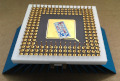
Here are some new photos, including the back. It doesn't look like there are any damaged traces.