VOGONS


Socket A: Aiming for the Stars!!!

Topic actions

Reply 440 of 459, by zuldan

User metadata
Rank Oldbie
Rank
Oldbie
_digitalbath wrote on 2026-07-08, 19:48:
I wouldn't use Kyocera capacitors. Chemi-con PSG, Nichicon PLG or Kemet 750/755/759 are more reliable in their real measured val […]
Show full quote
zuldan wrote on 2026-07-07, 01:34:

What do you think about doing this? Match the uF and voltage but still have low ESR.

I wouldn't use Kyocera capacitors. Chemi-con PSG, Nichicon PLG or Kemet 750/755/759 are more reliable in their real measured value.

Yellow is probably a Rubycon MBZ 6,3v/1800µF cap. I've replaced this position by a Chemi-Con PSG capacitor.
Pink has to be a polymer cap with a low ESR. Kemet may work but may also cause errors. Nichicon RN8 ( ESR 8 ) is here a possible way. My boards did work with Kemet 755 caps.
Rubycon YXG (dark puple and orange) is a general-purpose capacitor. They have to be replaced by electrolytic capacitors like Panasonic FR. Polymere caps may cause problems here. They are not crucial though.

Thanks digitalbath, I appreciate all the advice. All noted.

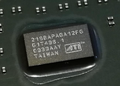
Could you also tell me what issues you experienced when using brainpower PCBs with the Winbond chips (post code errors maybe)? And is it better to use Samsung TCCD with the brainpower PCBs?
Reply 441 of 459, by Tzk

User metadata
Rank Newbie
Rank
Newbie

Regarding the caps: what digitalbath said.

In general (and thus not specific to that board) it's important to know the actual voltage at the caps and the ESR should match. depending on the exact purpose of the caps you may solder less bulk capacity and get away with it. Think of the ESR as the capability of the capacitor on how fast it can deliver energy to the components it supports. Lower ESR means faster reaction or delivery of energy. Now, this comes with upsides and downsides. Upside: faster response will result in less ripple voltage and thus better stability. Downsides: the mosfets which charge those capacitors must handle the higher charging current and the feedback loop (output voltage measurement and adjustment of regulation to get the desired voltage) may be hurt. Also leakage may be a bit higher on polymer caps than standard electrolytic caps.

That's the reason you can't just place ESR5 caps everywhere. In theory that should give best results regarding transient response and ripple voltage, but the board must be able to handle it. In practice some boards will, but some boards won't. You may get boards which just become hot and won't POST with ultra-low ESR caps.

Selection of replacement caps is always a decision for a single board. Sometimes you can replace 6.3V caps with 4V (for example cpu stage on several 462 boards), but if 6.3V is soldered on the 5V rail you better stay away from 4V caps for obvious reasons. Sometimes selecting 16V caps instead (for ex. Kemet A750 16V 2200uF over A750 4V 2200uF) even if it's only Vcore is a good choice. In this case the 16V got a little less ESR and fit the spec of their datasheet a bit better. The Kemet A750 4V 2200uF seem to miss their specs sometimes or at least got some kind of variance between pruduction batches.

zuldan wrote on 2026-07-08, 21:46:

Could you also tell me what issues you experienced when using brainpower PCBs with the Winbond chips (post code errors maybe)? And is it better to use Samsung TCCD with the brainpower PCBs?

It seems that brainpower PCB works best with low voltage chips which need clean routing and good shielding of the traces on the dram pcb. So TCCD, UCCC, Hynix, Infineon and the likes. For Winbond the standard Infineon AT-6 pcb (somewhat unexpectedly) works great. AT-6 is relabeled BH-6, so i've not transplanted the chips to another PCB. Single sided Hynix ETR (1x512mb) works great on brainpower B6U808 though, same for TCCD.

Last edited by Tzk on 2026-07-10, 04:46. Edited 1 time in total.

Reply 442 of 459, by _digitalbath

User metadata
Rank Newbie
Rank
Newbie
Tzk wrote on 2026-07-09, 04:24:

The Kemet A750 4V 2200uF seem to miss their specs sometimes or at least got some kind of variance between pruduction batches.

As far as I remember the 4V / 2200µF Kemets are fine. The 6,3V variant tends to have higher ESR values compaired to their specs.
If you are limited in space near the CPU socket, the 4V Kemets (for Vcore) may make sense to me. They're smaller then the 16V versions. Most of the times I use the 16V versions to be more flexible.

zuldan wrote on 2026-07-08, 21:46:

Could you also tell me what issues you experienced when using brainpower PCBs with the Winbond chips (post code errors maybe)? And is it better to use Samsung TCCD with the brainpower PCBs?

You can use Winbond chips on a BP PCB without any issues—the system will POST normally. However, overclocking results may not be as good.
Some time ago, I tested Infineon AT6 chips on a BP PCB and achieved worse results compared to the original PCB. After soldering the chips back onto a better-performing PCB, the previous results returned. I did solder only single sided sticks, what may be also a reason for it. Someone on the HWBot forums mentioned that single-sided Winbond modules on a BP PCB tend to achieve lower frequencies, whereas modules utilizing both sides of the PCB do not appear to be limited in the same way. However, I have not verified this myself.

As Tzk mentioned, the BP PCB seems to perform best at lower voltages (I'd say below 3.0 V). Most memory chips work very well with this PCB under those conditions. Winbond chips, on the other hand, generally require higher voltages to reach their full potential, so a different PCB may be a better choice in that case.
In my experience, most PCBs equipped with a larger number of ceramic capacitors perform reasonably well. The Corsair PCB with an alternating chip layout delivered the best results for me.

Reply 443 of 459, by zuldan

User metadata
Rank Oldbie
Rank
Oldbie
Tzk wrote on 2026-07-09, 04:24:
Regarding the caps: what digitalbath said. […]
Show full quote

Regarding the caps: what digitalbath said.

In general (and thus not specific to that board) it's important to know the actual voltage at the caps and the ESR should match. depending on the exact purpose of the caps you may solder less bulk capacity and get away with it. Think of the ESR as the capability of the capacitor on how fast it can deliver energy to the components it supports. Lower ESR means faster reaction or delivery of energy. Now, this comes with upsides and downsides. Upside: faster response will result in less ripple voltage and thus better stability. Downsides: the mosfets which charge those capacitors must handle the higher charging current and the feedback loop (output voltage measurement and adjustment of regulation to get the desired voltage) may be hurt. Also leakage may be a bit higher on polymer caps than standard electrolytic caps.

That's the reason you can't just place ESR5 caps everywhere. In theory that should give best results regarding transient response and ripple voltage, but the board must be able to handle it. In practice some boards will, but some boards won't. You may get boards which just become hot and won't POST with ultra-low ESR caps.

Selection of replacement caps is always a decision for a single board. Sometimes you can replace 6.3V caps with 4V (for example cpu stage on several 462 boards), but if 6.3V is soldered on the 5V rail you better stay away from 4V caps for obvious reasons. Sometimes selecting 16V caps instead (for ex. Kemet A750 16V 2200uF over A750 4V 2200uF) even if it's only Vcore is a good choice. In this case the 16V got a little less ESR fit the spec of their datasheet a bit better. The Kemet A750 4V 2200uF seem to miss their specs sometimes or at least got some kind of variance between pruduction batches.

What great information. That explains a lot. I guess it's a bit of trial and error with the board to see what works best.

Tzk wrote on 2026-07-09, 04:24:

It seems that brainpower PCB works best with low voltage chips which need clean routing and good shielding of the traces on the dram pcb. So TCCD, UCCC, Hynix, Infineon and the likes. For Winbond the standard Infineon AT-6 pcb (somewhat unexpectedly) works great. AT-6 is relabeled BH-6, so i've not transplanted the chips to another PCB. Single sided Hynix ETR (1x512mb) works great on brainpower B6U808 though, same for TCCD.

I've ordered some TCCD chips to play with on my PB PCB's. Hoping I'll have better luck getting the sticks working.

Reply 444 of 459, by zuldan

User metadata
Rank Oldbie
Rank
Oldbie
_digitalbath wrote on 2026-07-08, 19:48:

I wouldn't use Kyocera capacitors. Chemi-con PSG, Nichicon PLG or Kemet 750/755/759 are more reliable in their real measured value.

The only reason I mentioned Kyocera capacitors is because that's what have in stock. If I measured their specs with say a PEAK meter prior to installation, would that be good enough?

_digitalbath wrote on 2026-07-09, 05:59:
You can use Winbond chips on a BP PCB without any issues—the system will POST normally. However, overclocking results may not be […]
Show full quote

You can use Winbond chips on a BP PCB without any issues—the system will POST normally. However, overclocking results may not be as good.
Some time ago, I tested Infineon AT6 chips on a BP PCB and achieved worse results compared to the original PCB. After soldering the chips back onto a better-performing PCB, the previous results returned. I did solder only single sided sticks, what may be also a reason for it. Someone on the HWBot forums mentioned that single-sided Winbond modules on a BP PCB tend to achieve lower frequencies, whereas modules utilizing both sides of the PCB do not appear to be limited in the same way. However, I have not verified this myself.

As Tzk mentioned, the BP PCB seems to perform best at lower voltages (I'd say below 3.0 V). Most memory chips work very well with this PCB under those conditions. Winbond chips, on the other hand, generally require higher voltages to reach their full potential, so a different PCB may be a better choice in that case.
In my experience, most PCBs equipped with a larger number of ceramic capacitors perform reasonably well. The Corsair PCB with an alternating chip layout delivered the best results for me.

I had a terrible time getting trying to get the Winbond chips to work on the BP PCB's. I've reballed/replaced many GPU's in the past which is harder to do than install simple DDR1 chips but I could not get it to work properly.

I've ordered this PCB to have another go with the Winbond chips.

The attachment s-l1600 (1).webp is no longer available
The attachment s-l1600 (2).webp is no longer available

Reply 445 of 459, by zuldan

User metadata
Rank Oldbie
Rank
Oldbie

@digitalbath & @Tzk, I'm determined to get into the top 3 on the scoreboard. While I wait for new PCB's to arrive.....if I modify the SPD on my CMX512-3200XL (TCCD) chips and disable a rank to get 256MB per stick. Would that possibly allow me to go a bit higher in FSB or would the NF7 be too clever and still use 512MB on each stick?

The attachment IMG_0289.jpeg is no longer available

Reply 446 of 459, by _digitalbath

User metadata
Rank Newbie
Rank
Newbie
zuldan wrote on 2026-07-09, 10:01:

The only reason I mentioned Kyocera capacitors is because that's what have in stock. If I measured their specs with say a PEAK meter prior to installation, would that be good enough?

To be honest, I have no clue how to measure capacitors properly. As far as I know, you can't get accurate readings with a cheap tester. The test frequency is a critical factor here.I got most of my information about capacitors from a Hardwareluxx user named WMDK, who is an absolute expert on the topic.If I remember correctly, Kyocera AVX capacitors suffer from inconsistent ESR values. While they might work perfectly fine in some cases, they can also cause unexpected issues. It's a gamble, so I personally wouldn't risk it.

zuldan wrote on 2026-07-09, 10:01:

I had a terrible time getting trying to get the Winbond chips to work on the BP PCB's. I've reballed/replaced many GPU's in the past which is harder to do than install simple DDR1 chips but I could not get it to work properly.

For me, it's the other way around. I need to learn how to solder and reflow BGA chips. TSOP chips like DDR1 are much easier for me to solder.I use a flat tip and plenty of flux to solder the chips. To make sure all the pins are connected properly, I check every side with a magnifying glass (I'm getting older, and focusing on things up close is getting harder 😜 ). I look for solder bridges or poorly soldered pins, because a single unsoldered pin will prevent the system from booting.
Make sure the SPD values are correct. number of ranks and density

edit.

zuldan wrote on 2026-07-09, 10:07:

@digitalbath & @Tzk, I'm determined to get into the top 3 on the scoreboard. While I wait for new PCB's to arrive.....if I modify the SPD on my CMX512-3200XL (TCCD) chips and disable a rank to get 256MB per stick. Would that possibly allow me to go a bit higher in FSB or would the NF7 be too clever and still use 512MB on each stick?

I never tested it. Afaik Tzk did it.
Try higher alpha timings with TCCD sticks. It may help.

Some fun sticks just for science.

Reply 447 of 459, by Tzk

User metadata
Rank Newbie
Rank
Newbie
zuldan wrote on 2026-07-09, 10:07:

@digitalbath & @Tzk, I'm determined to get into the top 3 on the scoreboard. While I wait for new PCB's to arrive.....if I modify the SPD on my CMX512-3200XL (TCCD) chips and disable a rank to get 256MB per stick. Would that possibly allow me to go a bit higher in FSB or would the NF7 be too clever and still use 512MB on each stick?

Yes, you can use SPDTool and disable the second rank on 512mb TCCD sticks. Also yes, the board will detect it as 256mb stick afterwards. I tried this with Corsair XL sticks (0538 and 0542), worked but i didn't gain any additional FSB. I never tested why this was the case, two reasons came to mind: a) the disabled rank still causes load on the dram controller in the chipset and the vdimm power stage or b) the sticks just had avarage chips on both sides and maybe the weakest chip on the first rank.

in total i tried 6 TCCD sticks (2x XL 0538, 2x XL 0542 and 2x GEIL Ultra-X DDR400) and the best ones were the GEIL ones. That kit runs 300Mhz 2,5-4-3 on DFI Ultra-D (939), but still struggled at 2.5-3-3 250-255Mhz on several NF2 boards. The corsair didn't even reach 250, but stopped somewhere around 240-245Mhz. My conclusion was that TCCD simply isn't a good match for Nforce 2, but maybe i just didn't find the right settings or i didn't try hard enough.

Going for 250Mhz 2.5-3-3 with 512mb Hynix DT-D43 or or 2.5-4-4 with Hynix 256mb BT-D43 is waaaay easier and those are also a lot cheaper with good availability. Still king of NF2 is the mighty Hynix ETR, >275MHz 2.5-3-3 works. Or Winbond at 255-260MHz 2-2-2-5.

Reply 448 of 459, by tehsiggi

User metadata
Rank Oldbie
Rank
Oldbie

Hoping for some time next week to get some new scores. Also have to mod the other board as well.
But here's my take on the 12V PWR mod for the A7N8X. Files and stuff will land on github this weekend, so anybody can do the mod themselves.

See you around (hopefully with a score to kick zuldan out of the top 5 again 😁)

The attachment vrm_complete.jpeg is no longer available

AGP Card Real Power Consumption
AGP Power monitor - diagnostic hardware tool
Graphics card repair collection

Reply 449 of 459, by _digitalbath

User metadata
Rank Newbie
Rank
Newbie

Nice and clean 12V mod. I like it!

Reply 450 of 459, by tehsiggi

User metadata
Rank Oldbie
Rank
Oldbie
_digitalbath wrote on 2026-07-11, 10:13:

Nice and clean 12V mod. I like it!

Thanks, much appreciated. I'm very happy with the result.


Regarding the overall progress: I at least got 10 minutes yesterday to perform the BIOS Chipset VDD mod for the same board, so I can adjust the chipset voltage via software.
Luckily, Tzk, digitalbath, Sandman and others did a lot of tremendous work and research in the hardwareluxx forum.. (too bad my old account got deleted at some point, I'm always too lazy to register again 😁)

With the mod in place, the 243MHz FSB wall fell immediately and I got at least to 255 yesterday in a quick test:

The attachment a7n8x_1_255_fsb_3.JPG is no longer available

I know, for wild ones here nothing to write home about, but for the "in-between" efforts I can do right now, I'm pretty happy.


This leaves the question about memory. For my FSB testing yesterday I used very relaxed timings and was able to boot with that. However we all know that that's not sufficient.
On my other board I have the Vmem mod installed and can go to 3.5V Vmem without issues. I'll rework the feedback loop next week hopefully to make sure it's more stable, as noted in some extreme OCing by Tzk.

So Vmem should not be an issue. (If at all, I'll just quickly design myself a more powerful piggyback board and replace the whole Vmem regulator section)

The following memory does lay around right now (most of it was done with the copper OCZ kit so far)

The attachment ram_cmx256a-3500c2-xms3502v11.jpg is no longer available

Supposedly BH5, haven't pulled the heatsinks of so far. Got 2 sticks.

The attachment mt8vddt3264AG.jpg is no longer available

Micron, 46V32MB-5B G - Got 2 sticks.

The attachment ram_ocz400512PFDC-K.jpg is no longer available

Chips on here are Infineon HYB25D256800CE-5 - got 4 sticks of it

The attachment ram_ocz4001024ELDCPE-K.jpg is no longer available

Chips unknown so far.. - got 4 sticks of it

Anything useful? 😁

AGP Card Real Power Consumption
AGP Power monitor - diagnostic hardware tool
Graphics card repair collection

Reply 451 of 459, by Tzk

User metadata
Rank Newbie
Rank
Newbie

Atlan1980 (Hwluxx) deserves full credit for the Vdimm feedback rework. My massive vdimm loss under load was completely gone after i modded the divider. However this was an issue with high vdimm (>3.5V) and 512mb BH-5 sticks only. If you’re using 2x256mb you mostly get away without it.

255Mhz is already good, in the end it all comes down to silicon lottery. Fingers crossed you found a decent board. I got about 20 NF2 boards and only 2 or 3 are considered very good. My Ultra B doesn’t pass anything higher than 250, same as my NF7.

Regarding your rams, the Corsair 3500C2 is BH-5, no need to pull the spreaders. I’d try these first. The OCZ kits could be anything. I guess you have to pull the spreaders.

The piggyback PCB looks great, I love the idea. Nice work! If you design something similar for Vdd and Vdimm, please show it off. I’d love to know if this will give additional OC headroom.

Reply 452 of 459, by tehsiggi

User metadata
Rank Oldbie
Rank
Oldbie

Thanks for all the input. The copper kits use HYB25D256800CE-5 and I've just lifted the heatspreader from the platinum kit - chips are Aeneon AED83T500.

I'll go and check the BH-5 kit first. Perhaps I'll slap the Vmem mod onto that board today and use the afternoon on/off to check them out.

AGP Card Real Power Consumption
AGP Power monitor - diagnostic hardware tool
Graphics card repair collection

Reply 453 of 459, by tehsiggi

User metadata
Rank Oldbie
Rank
Oldbie

Okay, i tried around a little and did a dirty Vmem mod. The Athlon xp 2800 isn't the best clocker and I don't have the CPU Vmod on it. Plus a flimsy xilence air cooler. Not great for scores, but good enough to check the memory.

So far I was able to achieve 245 with 2-2-2-5 on the BH5 with Vmem at 3,22V - I'm having a lot of fun with that board right now.

The attachment IMG-20260712-WA0007.jpg is no longer available

From a stability point of view this runs already way better than anything before. On the other board in never able to get the memory so high with CL2. I suspect the power contraints really hampered success there. Can't wait to have both boards fully modded.

So I'll see if I can get the memory to the 255er mark, which would be insane to me.

Next step then is better CPU and putting my watercooling on it.

AGP Card Real Power Consumption
AGP Power monitor - diagnostic hardware tool
Graphics card repair collection

Reply 454 of 459, by Tzk

User metadata
Rank Newbie
Rank
Newbie
tehsiggi wrote on Yesterday, 10:42:

Thanks for all the input. The copper kits use HYB25D256800CE-5 and I've just lifted the heatspreader from the platinum kit - chips are Aeneon AED83T500.

I'll go and check the BH-5 kit first. Perhaps I'll slap the Vmem mod onto that board today and use the afternoon on/off to check them out.

The CE based kit will work, but don’t expect much. Usually Infineon/Qimonda/Aeneon 256mbit chips clock alright, but 512mbit based chips clock better. So if your 512mb stick is double sided, then it’s 256mbit chips. If single sided, then 512mbit chips. 512mbit CE-5 or DE-5 will work. 256mbit usually hits a wall around 245-250Mhz 3-4-4-8.

I expect your Aeneon to clock better, as this seems to be 512mbit.

Regarding your BH-5 result, 245Mhz at 3.22V sounds about right. Maybe Vdimm is already holding you back. Also 619XT Romsips are a solid choice, you could try something ED based to check what works better on your board. I can also recommend to use the mighty Nforce 2 Xtreme Tweaker by Infrared (irusanov on GitHub) if you‘re looking for the last few MHz FSB or that little extra stability to complete a benchmark.

Simple Vdimm Mod will easily reach 3.8V on A7N8X, as it’s fed off 5V.

Reply 455 of 459, by tehsiggi

User metadata
Rank Oldbie
Rank
Oldbie

Thanks for all the input, very much appreciated.

As for my plans - well, Murhpy get's you all the time.
Board No1 (the one I've been testing with the last week) now stubbornly refuses to boot. Similar behavior to what I had once before.
Post-card behavior looks like "no-power" first time bootup behavior. Then the post code is stuck at "25 24" (basically the same as during normal operation).

I had it a couple of times that the board didn't like a cold "overnight" boot and then the second attempt just worked fine, but this is just odd. There's also no overclock applied right now.
Tried 4 GPUs (all known working) incl. PCI one. No luck.. *sigh*

I guess it's debugging time first.. not sure how far I get this week, as next week vacation starts.

Again, all the knowledge gained here is much appreciated! Thanks!

AGP Card Real Power Consumption
AGP Power monitor - diagnostic hardware tool
Graphics card repair collection

Reply 456 of 459, by Tzk

User metadata
Rank Newbie
Rank
Newbie

Try this:
Remove ram, then boot without ram installed. Power off via power button/soft-off (do not flip psu switch). Reinstall ram (don’t use Winbond BH-5 as it doesn’t support CL3!). Reboot. Try different sticks, one stick in slot 1 or 2 should do.

post code 25 is ram detection, so I suspect it’s either trying to boot timings which the ram doesn’t support, or the ram needs a reinsertion.

I’ve had issues (re)booting when the system halted or I got a blue screen during benching. Lower clocks were unstable afterwards, even 180-200Mhz fsb. The solution was the procedure stated above… anything which will force the board into “fail-safe” boot (post at fsb100 multi 6) should do the trick.

Reply 457 of 459, by tehsiggi

User metadata
Rank Oldbie
Rank
Oldbie
Tzk wrote on Today, 10:17:
Try this: Remove ram, then boot without ram installed. Power off via power button/soft-off (do not flip psu switch). Reinstall r […]
Show full quote

Try this:
Remove ram, then boot without ram installed. Power off via power button/soft-off (do not flip psu switch). Reinstall ram (don’t use Winbond BH-5 as it doesn’t support CL3!). Reboot. Try different sticks, one stick in slot 1 or 2 should do.

post code 25 is ram detection, so I suspect it’s either trying to boot timings which the ram doesn’t support, or the ram needs a reinsertion.

I’ve had issues (re)booting when the system halted or I got a blue screen during benching. Lower clocks were unstable afterwards, even 180-200Mhz fsb. The solution was the procedure stated above… anything which will force the board into “fail-safe” boot (post at fsb100 multi 6) should do the trick.

Thanks! Did that dance already a couple of times and at some point it finally decided to come back to life again.
Pretty suspect.

The attachment a7n8x_1_240_fsb_3d_1.JPG is no longer available

Not much tweaking time in the lunch break. But hey, here it goes! Number 5 again 😉 Sorry Zuldan 😁

That XP-M 2500 doesn't enjoy high clocks it seems.. we'll find someone better.

AGP Card Real Power Consumption
AGP Power monitor - diagnostic hardware tool
Graphics card repair collection

Reply 458 of 459, by tehsiggi

User metadata
Rank Oldbie
Rank
Oldbie

Some more headroom.. the 23k will fall tomorrow.. I'm certain.. then I can go on vacation in peace and plan further steps..

The attachment a7n8x_1_240_fsb_3d_2.JPG is no longer available

AGP Card Real Power Consumption
AGP Power monitor - diagnostic hardware tool
Graphics card repair collection

Reply 459 of 459, by supercordo

User metadata
Rank Member
Rank
Member

Ill update the score tomorrow then. OC the video card!!!!!