First post, by ajacocks
- Rank
- Member
Folks,
I also asked this on the VCF forum, but thought that this group might well have more diverse PC knowledge.
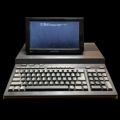
I lucked in to an empty chassis for an Orchid Portable PCIII. This is the same chassis as @polishvito posted about a few years ago. Mine is different in that it has a paperwhite passive matrix VGA LCD instead of his CGA plasma display. Interestingly, Orchid systems made the chassis as a Compaq Portable III/386 clone, and still exists today. They references that machine on their current site.
I've already found, in my existing collection, an SBC (Advantech PCA-6144S 486 SBC) and a video card that supports greyscale passive panels (Advantech PCA-6653 ). I ordered a backplane suitable for the chassis and tested the SBC and video card successfully.
The tough part is that the panel is seemingly undocumented online (I have searched a LOT), and so I have had to beep out the connections between the LCD itself, the interposer board that provides signal and power to it, and to the backlight controller PCB. My results are in this Google sheet.
Any assistance in identifying the pin mapping between the 16 pin ribbon cable that provides signal, the 5 pin molex cable that provides power, the 44 pin connector on the PCA-6653, and the PSU, would be appreciated. The manual page for the PCA-6653 that lists the connector pinout is on archive.org. The manual for the SBC, should that be useful, is here.
Thanks!
- Alex