VOGONS


Asus TX-97 No Post

Topic actions

First post, by Retronerd878

User metadata
Rank Member
Rank
Member

I'm trying to debug an Asus TX-97 motherboard that doesn't want to POST. The post analyzer card doesn't show any post codes.
I'm using an MMX CPU and the voltage is set to 2.8V. However, from what I measured, the CPU gets only 1V. Any Ideas?
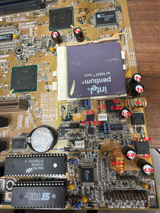
Here is a pic with the voltages I measured.

Reply 1 of 18, by Retronerd878

User metadata
Rank Member
Rank
Member

I inspected the motherboard an it looks clean with no physical damage. Also, I updated the bios on an external programmer. No luck!
I know that this board has a history of bad power delivery but don't know exactly what to check.
I'm thinking of ordering the hip6008cb controller and replacing it, if someone doesn't have a better idea.

Reply 2 of 18, by rasz_pl

User metadata
Rank l33t++
Rank
l33t++

wiretap made a schematic when designing pentium pro VRM with HIP6008 Re: Pentium Pro VRM
Schottky diode Asus Q1505 PBYR1035B - wiretap CR2 MBR2535
Mosfet Asus Q1503? cant see markings - wiretap Q1 IPB042N03

basic check would be
- are VID jumpers all ok and giving solid expected logic levels?
- with no cpu measure resistance to ground on L1502
- buzz mosfet and diode for shorts
- make sure HIP6008 pins 11 and 16 connect to output between output coil
- and its FB and Comp inputs are connected thru good resistors to output
- maaaybe, but Im lukeworm on that, remove output capacitors and measure or replace (for test)

Do you have an oscilloscope to look at the waveform going into transistor? see that circled 2 wit an arrow pointing at the leg of transistor - thats its gate where HIP6008 should be driving it with steady healthy signal.

in not sure what Q1506 is and whats it doing

https://github.com/raszpl/sigrok-disk FM/MFM/RLL decoder
https://github.com/raszpl/FIC-486-GAC-2-Cache-Module (AT&T Globalyst)
https://github.com/raszpl/386RC-16 ram board
https://github.com/raszpl/Zenith_ZBIOS Zenith Z-386 MFM-300 ZBIOS disassembly

Reply 3 of 18, by Retronerd878

User metadata
Rank Member
Rank
Member

- Jumpers are set correctly. Checked with the silkscreen on the motherboard as well
- Resistance to ground (without CPU) on choke near CPU is 400 kohms on both sides
- No shorts on mosfets or diodes
- Pin 16 and 11 have continuity to choke near CPU
- The 2 nearby resistors are good. Actually I measured a lot of them in-circuit and none are shorted or open.
- Measured with oscilloscope the tab marked with number 2 (the one which measured 1.8V) and it's no a clean waveform. It's continuously switching. Pics attached

Reply 4 of 18, by rasz_pl

User metadata
Rank l33t++
Rank
l33t++

is the cpu known working one?
dont measure with cpu inserter, solder 20-40 ohm resistor on output capacitor to ground so there is some load

> Jumpers are set correctly. Checked with the silkscreen on the motherboard as well

yes, they are set correctly, but do they all conduct well? switch all to 1-2 for a test, should give 2.7v? with resistor as load play with those vid jumpers and look if output voltage changes at all

you can try soldering another capacitor in parallel with one of the output caps, any random lowesr ~1000uF will do

can you set timebase to 10 or 1ns? and set a trigger so it stops acquisition so we can see whats going on
I dont know how you read that, whats the volts/div here? where is zero? surely not in the middle of that waveform

and check hip is getting proper supply on pin 14

https://github.com/raszpl/sigrok-disk FM/MFM/RLL decoder
https://github.com/raszpl/FIC-486-GAC-2-Cache-Module (AT&T Globalyst)
https://github.com/raszpl/386RC-16 ram board
https://github.com/raszpl/Zenith_ZBIOS Zenith Z-386 MFM-300 ZBIOS disassembly

Reply 5 of 18, by Retronerd878

User metadata
Rank Member
Rank
Member

The CPU is a known working one.
All the resistance measurements were done without CPU.
Jumpers work fine, i checked on the back of the board and they bridge correctly.
The oscilloscope measurements were done with CPU installed.
I'm not really that savvy with the oscilloscope. I just use it to tell if a crystal oscillator is working. I pin the probes and press auto button.
I can go as fast as 5ns but the the graph is so stretched that is basically a flat line. Here is a more revealing capture I think.

I'm not going to solder some dummy loads. I can try a quick full recap if you are suspicious of the caps, as there are only 10 caps, but they look pretty good though.

Reply 6 of 18, by Retronerd878

User metadata
Rank Member
Rank
Member

Just did a full recap. Measured all the old caps and they were all withing spec. Some were as low as 800 uF, but I don't think that's an issue. Replaced them with new Panasonic ones and problem is still there.

One thing that bugs me. On the POST analyzer card, regardless if it's plugged into PCI or ISA slot, the 3.3V LED is not lit up.

Reply 7 of 18, by rasz_pl

User metadata
Rank l33t++
Rank
l33t++
Retronerd878 wrote on 2026-11-01, 14:12:

Jumpers work fine, i checked on the back of the board and they bridge correctly.

I meant to change them up to see if you get different output voltage. Will tell us if regulation is working and reg getting some feedback - but since Vgs readings are bad you can forget about Vid jumpers for now

Retronerd878 wrote on 2026-11-01, 14:12:

I can go as fast as 5ns but the the graph is so stretched that is basically a flat line. Here is a more revealing capture I think.

yes, this is a better capture. Previously funny scope was pretending to do Persistence by overlaying mess on top of each other without good/visible color/brightness grading

Now we can see reg is doing something, we still cant see what its doing because
what is the vertical scale?
where is zero? is it really driving 1V and then getting -1V on the gate? or is the reading bad because funny multimeter scope?

if its really 1V then HIP6008 is getting bad power on pin 14 (should be 12V) or HIP6008 driver supply pin 13 is not getting enough power. Its hard to tell from the picture (small resolution, dirty, bad angle) how the Boot is powered. Is it linked to 12V or is there a bootstrap circuit (diode and capacitor wired to pin 13)?

im HIP6008 is working, but not getting power to properly open mosfet

Retronerd878 wrote on 2026-11-01, 14:12:

I'm not going to solder some dummy loads.

you can stick a resistor in CPU socket without soldering. Since reg is not producing correct voltage you are risking your cpu - what if it decides to pass 5V to your MMX?

Retronerd878 wrote on 2026-11-01, 14:12:

I can try a quick full recap if you are suspicious of the caps

Im not, but soldering one good cap in parallel is enough to verify

Retronerd878 wrote on 2026-11-01, 14:12:

as there are only 10 caps, but they look pretty good though.

only 4 are pertinent 😀

Retronerd878 wrote on 2026-11-01, 14:12:

Some were as low as 800 uF

capacity wouldnt be the problem, ESR aka how fast can cap react to changes in load without itself becoming a load. This is why you dont need to change all caps to determine if that is the issue - soldering even just one good cap creates low resistance path overriding all the bad ones.

Retronerd878 wrote on 2026-11-01, 14:12:

>One thing that bugs me. On the POST analyzer card, regardless if it's plugged into PCI or ISA slot, the 3.3V LED is not lit up.

its a different 3.3V 😀 ISA never had any and PCI gained it only around Pentium 2/ATX era
cpu 3.3V is its own separate power circuit


https://github.com/raszpl/sigrok-disk FM/MFM/RLL decoder
https://github.com/raszpl/FIC-486-GAC-2-Cache-Module (AT&T Globalyst)
https://github.com/raszpl/386RC-16 ram board
https://github.com/raszpl/Zenith_ZBIOS Zenith Z-386 MFM-300 ZBIOS disassembly

Reply 8 of 18, by jh80

User metadata
Rank Member
Rank
Member

I also have a TX-97 that appears to be in perfect condition but I could never get it to post. Recapping and reflashing BIOS had no effect.

There are numerous posts on Vogons from people reporting similar (these threads seem to pop up frequently).

Do these boards suffer from some obscure, common failure point, or were they just such popular boards that we hear about them more? Unsure. But I'm hoping someone eventually finds a common failure point so I can fix mine.

Reply 9 of 18, by rasz_pl

User metadata
Rank l33t++
Rank
l33t++

TX was the first consumer bga chipset from Intel and one of the first bga chipsets board manufacturers ever used. First would be 430HX, but that was high end so not a lot of boards.
BGA chips are very sensitive to bending pcb, like pushing in ram "to click" inside the case Re: Aopen AP53 with i430HX and Ami Bios: Flash is write-protected?

https://github.com/raszpl/sigrok-disk FM/MFM/RLL decoder
https://github.com/raszpl/FIC-486-GAC-2-Cache-Module (AT&T Globalyst)
https://github.com/raszpl/386RC-16 ram board
https://github.com/raszpl/Zenith_ZBIOS Zenith Z-386 MFM-300 ZBIOS disassembly

Reply 10 of 18, by kingcake

User metadata
Rank Oldbie
Rank
Oldbie
jh80 wrote on 2026-11-02, 00:28:

Do these boards suffer from some obscure, common failure point, or were they just such popular boards that we hear about them more? Unsure. But I'm hoping someone eventually finds a common failure point so I can fix mine.

Yes, it's the chip that controls power/clock iirc. This was well known back in the day.

Reply 11 of 18, by Retronerd878

User metadata
Rank Member
Rank
Member

Old caps were 800-950 uF and 150-200 mOhm ESR. New caps are 900-950 uF and 100-120 mOhm ESR.
Tested the input voltage on the HIP chip and it gets 12V correctly.

I used a non MMX CPU and changed the jumpers accordingly and now the voltage measured at the choke is 0.8V.
So:
Set to 2.8V - Measures 1V
Set to 3.4V - Measures 0.8V

Reply 12 of 18, by majestyk

User metadata
Rank Oldbie
Rank
Oldbie

The system monitoring / controlling chip NSC "LM78CCVF" is able to enable / disable a 5V supply voltage via a MOSFET, if certain conditions that it monitors are not met. The MOSFET at the input of the Vcore VRM (right behind the decoupling toroid) _could_ act as such a switch if it was controlled by the LM. Voltage drops from 4.9 (5) V to 1V there -> no Vcore no matter what the "HIP" and the step down circuit do.
If this is true, a monitoring input condition could be the cause or the LM itself could be faulty.

Reply 13 of 18, by rasz_pl

User metadata
Rank l33t++
Rank
l33t++
Retronerd878 wrote on 2026-11-02, 06:32:

Old caps were 800-950 uF and 150-200 mOhm ESR. New caps are 900-950 uF and 100-120 mOhm ESR.

meaning both perfectly fine

Retronerd878 wrote on 2026-11-02, 06:32:

Tested the input voltage on the HIP chip and it gets 12V correctly.

where?
pin 14 is HIP supply - that makes it run
pin 13 is HIP driver supply (BOOT) - that lets it properly drive upper mosfet.

The attachment hip.jpg is no longer available

To properly open something like BUZ103 (still dont know exact mosfet used on your board) with Drain-Source voltage of 5V (as you emasured) you need Gate-Source voltage of >10V. In order to be able to apply >10V HIP needs at least 12V on its BOOT pin supplying its gate driver.

does pin 13 have 12V? can you put a scope on that pin?

Retronerd878 wrote on 2026-11-02, 06:32:

Set to 2.8V - Measures 1V
Set to 3.4V - Measures 0.8V

so the control part of HIP tries to do something

majestyk wrote on 2026-11-02, 07:23:

The system monitoring / controlling chip NSC "LM78CCVF" is able to enable / disable a 5V supply voltage via a MOSFET, if certain conditions that it monitors are not met.

LM78CCVF doesnt do any control, it only does monitoring and alarms. Alarms are signaled with interrupts (NMI / SMI) and require running CPU to program and receive them.

"At power on, the ADC is stopped and INT__Clear is
asserted, clearing the SMI and NMI/IRQ hardwire outputs."

majestyk wrote on 2026-11-02, 07:23:

The MOSFET at the input of the Vcore VRM (right behind the decoupling toroid)

which one?
IMG_9948.jpeg
Am I reading it wrong? to me it looks like
L1501 together with input caps provide EMI Filtering, what you called 'decoupling toroid'
Q1503 is the main switching mosfet
Q1505 Schottky diode
L1501 main output inductor

and after some more thinking Im guessing
Q1506 (between BF jumpers and L1501) is driven by some analog magic, U1502 LMsomething comparator, when single rail CPU is detected. It links 3.5V generated by Q1508 with main VRM.

https://github.com/raszpl/sigrok-disk FM/MFM/RLL decoder
https://github.com/raszpl/FIC-486-GAC-2-Cache-Module (AT&T Globalyst)
https://github.com/raszpl/386RC-16 ram board
https://github.com/raszpl/Zenith_ZBIOS Zenith Z-386 MFM-300 ZBIOS disassembly

Reply 14 of 18, by Retronerd878

User metadata
Rank Member
Rank
Member

Both pins 13 and 14 measure 12 V.

Would it be reasonable to assume that replacing the HIP chip is a good starting point for troubleshooting?

Reply 15 of 18, by kingcake

User metadata
Rank Oldbie
Rank
Oldbie
Retronerd878 wrote on 2026-11-02, 17:27:

Both pins 13 and 14 measure 12 V.

Would it be reasonable to assume that replacing the HIP chip is a good starting point for troubleshooting?

There was a chip notorious for failing on these boards, and I'm pretty sure that's it.

Reply 16 of 18, by rasz_pl

User metadata
Rank l33t++
Rank
l33t++

this leaves four possibilities

1 OCSET is being triggered by shorted resistor between pin 1 and 5V. Measure resistance between pin1 and 5V (circled 4). R1502 C1501. Imo this would shut down oscillations or cause chiccups so most likely not it.

2 feedback is bad. R1503 R1504 and something else, but that would also shut down oscillations so also not it

3 Mosfet Gate-Source is shorted. Resistance between Pins 11 and 12. can be it

4 HIP gate driver is blown. also can be it. Easier to replace than building external circuit to verify 🙁. You could try lifting Q1503 leg 1 (the one with circled 2), putting scope on HIP Pin 12 and setting it to triggers on first pulse, then turning stuff ON. if HIP is fine Pin 12 should jump to 12V for maybe couple of cycles before it shuts down (because no output voltage).

https://github.com/raszpl/sigrok-disk FM/MFM/RLL decoder
https://github.com/raszpl/FIC-486-GAC-2-Cache-Module (AT&T Globalyst)
https://github.com/raszpl/386RC-16 ram board
https://github.com/raszpl/Zenith_ZBIOS Zenith Z-386 MFM-300 ZBIOS disassembly

Reply 17 of 18, by Retronerd878

User metadata
Rank Member
Rank
Member

Ordered some HIP chips. I'll report back if there is any progress when i get them and replace the one on the board.

Reply 18 of 18, by mockingbird

User metadata
Rank Oldbie
Rank
Oldbie
Retronerd878 wrote on 2026-11-03, 13:06:

Ordered some HIP chips. I'll report back if there is any progress when i get them and replace the one on the board.

I don't think the Aliexpress chips are real... I swapped mine with one of them, didn't help. But if they are, please do let me know so I can buy one from you.

mslrlv.png
(Decommissioned:)
7ivtic.png