VOGONS


Reply 60 of 85, by retro games 100

User metadata
Rank l33t
Rank
l33t
Jepael wrote:

You could buy some connectors or cables which you could use to convert whatever connector on your speakers and splice up the cable to separate signal wires. You could then screw the ground wire under PC case screw, and have a signal lead hanging loose which you could poke around the card.

I'm afraid I don't understand this part of the testing instructions. I thought that I used the tip section of the multimedia speakers plug to probe the Adlib sound card. Is that not the case? Perhaps what I need to do is this -

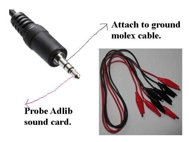
Get 2 crocodile/alligator leads with clips. One red, and the other black. Attach the black croc clip lead to the ground sleeve section of the speaker plug. The other end of this black lead goes to the black ground part of a PSU molex cable. Now, get a red croc clip, and attach it to the very end of the speaker plug. The other end of the red lead is used to probe the Adlib card. Is that correct? Thanks a lot for any advice. BTW, I have ordered the croc clips.

leads.jpg

Reply 62 of 85, by retro games 100

User metadata
Rank l33t
Rank
l33t

Ah thanks a lot! I'm itching to begin testing again. Hopefully, a pair of croc clips will arrive in the post tomorrow morning..

Edit: I forgot to ask something. On the "probe end" of the red croc clip, which is the one used as a probe on the sound card, can I put a thin/fine piece of metal in its "mouth". For example, a paperclip. This is to make the probe part of the red croc clip small and fine, as opposed to a "fat and closed" croc mouth.

Reply 63 of 85, by MatthewBrian

User metadata
Rank Member
Rank
Member
retro games 100 wrote:

Edit: I forgot to ask something. On the "probe end" of the red croc clip, which is the one used as a probe on the sound card, can I put a thin/fine piece of metal in its "mouth". For example, a paperclip. This is to make the probe part of the red croc clip small and fine, as opposed to a "fat and closed" croc mouth.

As long as it is conductive, you can.

I don't know how conductive is your paper clip as some paperclips are more conductive than the others depending on the material. You might better put a thin nail rather than a paperclip as nail is usually more conductive than a paperclip (it is usually made of Fe) so it would not really 'disturb' the signals by adding some resistance to it.

Last edited by MatthewBrian on 2012-01-09, 11:31. Edited 2 times in total.

Reply 64 of 85, by retro games 100

User metadata
Rank l33t
Rank
l33t

Thanks a lot. I'm sure I've got a small nail somewhere, and my croc leads have arrived, but I may not begin testing immediately. The reason is because I asked about this topic on the vintage-computer forum, here. A guy called Chuck responded, and suggested that I use a capacitor, which I haven't bought yet. I'm waiting for clarification about this on that website...

Reply 65 of 85, by Jepael

User metadata
Rank Oldbie
Rank
Oldbie

The capacitor value he suggested is very low for audio frequencies.

Assuming the amplifier has input impedance of 10kohms, the suggested 0.01uF capacitor has too low value in my opinion, because it sets the cutoff frequency to about 1600Hz, meaning you won't hear much bass. On the other hand, the DC pop heard when connecting the wires is very short as the capacitor charges quickly.

My suggestion would be a 1uF capacitor so the cutoff frequency is about 16Hz (again assuming 10k amplifier input).

But as said before, all amplifiers should have DC blocking caps on their input already, and it should be safe to connect to buffered DAC output which only has 2.5V of DC bias. So to be extra safe, you could buy a capacitor or salvage one from some old broken equipment for measuring filter outputs that have the about 6V DC bias.

Taking +/- 12V supply voltages into consideration, you might want to be sure and use capacitor voltage rating of at least 16 volts, but there is no harm if you get higher voltage rating like 25V or 50V or whatever there is.

So far the DC measurements indicate that the DAC midpoint voltage is coming out and buffered back in OK, and DAC output has this midpoint voltage when not playing anything and it is also buffered OK. This verifies DC operation of the DAC chip bias and two out of the four op-amps, but does not verify AC operation or DAC output.

To see the DAC output is actually working, maybe play some audio to see if you can measure that the voltage actually changes. When audio is playing, you could also try measuring on AC voltage scale, if DC measurements show no changes in voltage.

But I think you should do the multimeter measurements of filter output DC and AC voltages as well when audio is playing.

Reply 68 of 85, by Jepael

User metadata
Rank Oldbie
Rank
Oldbie

Since it is a electrolytic capacitor, make sure you connect it the right way around. Because amplifier should have 0V bias and every audio signal on Adlib board has positive bias, you should connect the negative side with a lot of dashes (minus signs) to amplifier, and positive side (no dashes or minus signs) to Adlib.

Reply 69 of 85, by retro games 100

User metadata
Rank l33t
Rank
l33t

OK, thanks a lot! BTW, it is much easier and cheaper (but admittedly slower) for me to wait 24 hours for the part from an ebay seller to arrive, than to travel in to the nearest city and purchase parts.

Reply 71 of 85, by retro games 100

User metadata
Rank l33t
Rank
l33t

Success! I received the caps this morning, and hooked everything up accordingly. I tried test #6, which was to probe pins 4 and 6 of U8, and I can hear music coming from the Adlib Jukebox program!

I will now finish off tests numbered 7-9, and report back here ASAP..

Reply 72 of 85, by retro games 100

User metadata
Rank l33t
Rank
l33t

I have completed tests numbered 7,8 and 9. For these last 3 tests, I didn't do any voltage measurements. Instead, I only did audio tests, to try and hear sound. Tests 7,8 and 9 all passed! I can hear Adlib music. However, I did not do the very last test within test #9, because I am unsure which solder spots to put the probe on to. The test I am unsure about is this one:

(taken from test #9) The big capacitor C18 blocks DC so amplified audio is available after it and on the audio output connector.

Please can you explain where these solder spots are? Thanks very much!

Reply 76 of 85, by retro games 100

User metadata
Rank l33t
Rank
l33t

Success. Thanks a lot, I have completed all of the audio tests. Every audio test works. Also, the volume control dial works. So, with the probe on either of the 2 solder spots close to the headphone plug, I can hear the music getting louder or softer, when I turn the volume dial in one direction, and then in the other direction.

I quadruple-checked the headphone port again, by plugging in some working headphones, and I can hear no sound. So, the headphone plug appears to be faulty. I now need to expand my admittedly mediocre "hands on skills", to include headphone plug replacement! Please can you gurus give me some advice as to what tools I need to purchase. For example, do I need to desolder, and then solder in a new headphone plug?

Thanks very much for all of the really excellent and interesting comments made so far.

Reply 77 of 85, by Jepael

User metadata
Rank Oldbie
Rank
Oldbie

You mean the connector on Adlib board is faulty and needs replacement?

Well after all that trouble it was so easy, I guess we should have started from the easiest end - but after all, it is the last measurement that determines what is broken, as no measurements need to be done after that :) I guess you can fix it yourself so I won't be getting an Adlib into my hands any time soon - unless someone else wants me to fix their Adlib :) I guess I have to rig a similar filter to an OPL3 chip for my experiments then to get that authentic sound (most OPL3 outputs are unfiltered on sound cards).

By the way, are you absolutely sure you used a stereo connector (plug with tip, ring and sleeve) like on your multimedia speaker? Because using a mono connector (plug with only tip and sleeve) will shortcut the right channel to ground (ring to sleeve), also affecting heavily to left channel (tip) output.

Reply 78 of 85, by retro games 100

User metadata
Rank l33t
Rank
l33t

Yes, I guess it is called a "connector". It's the plug that has a red arrow pointing at it, in the image below. I think it's the only component on the card that doesn't work. I wonder if I can buy a new one, from an electronics shop? When I search online at places like Farnell for "headphone", the search results returned are obvious, but not what I am looking for.

BTW, the headphones that I tried in the card's "connector" were stereo headphones.

Attachments

  • faulty.jpg
    Filename
    faulty.jpg
    File size
    19.81 KiB
    Views
    1177 views
    File license
    Fair use/fair dealing exception

Reply 79 of 85, by Ace

User metadata
Rank Oldbie
Rank
Oldbie

Is it possible the plug is actually a MONO plug? I remember getting absolutely no sound on an old CRT TV with a headphone jack on it because I was using Stereo headphones on a Mono headphone output and needed a Mono to Stereo(well, dual Mono) converter plug to actually hear anything. You may want to try looking for something like that before you actually replace the jack.

Creator of The Many Sounds of:, a collection of various DOS games played using different sound cards.