You took pretty good pics of the internals, congrats! Let's vivisection it.
The juice comes from the wall and first meets the input filtering section, which protects the PSU fron electrical fluctuations and noise coming from the wall, and prevents EMI and RFI (electromagnetic and radiofrequency interference) produced by the PSU from affecting other electronic gadgets in the house.
The worst of the gutless wonders either completely lack any transient filtering or have very little of it, to pinch a penny here and there (like the Brazilian PSU linked above, that has just two Y-caps and nothing more).
This PSU has two common mode chokes (the donuts with copper wire wrapped around), two X-capacitors (yellow boxes), but just one Y-capacitor (light blue lentil with two legs at the corner) when there should be two Y-caps at the least. It has however a ferrite bead in the mains wires, which is a rare touch amongst cheap PSUs:

The rule of thumb for decent input filtering is at least two chokes, two X-caps and two Y-caps. This PSU more or less manages it, and the reason is no other than pressure from current european laws on EMI/RFI.
Next comes the rectifier bridge, which as its name implies rectifies the juice from 230 volts AC to ~325 volts DC. Here they've used four discrete diodes, more penny pinching:

Discrete diodes can't be heatsunk, and laying so low on the ground they catch little breeze, hence they might overheat, derate and blow. A monobloc bridge with heatsink is much better, but cost more pennies.
Note also that the board is silkscreened for a passive PFC coil, which is absent. More cost cutting.
Next come the primary capacitors, which are sometimes called 'the big caps', but not in this case:

Those stumpy caps are marked '470uF' but they are so small that I wouldn't be surprised at all it they were fakes of less real capacitance. More penny pinching. Such undernourished primary caps are bad medicine for ripple handling and power delivery. Being cheapo brand and temp rated at 85C instead of 105C doesn't help either.
As is tradition with cheap PSUs the heatsinks are anoxerically thin (aluminium costs pennies). This is the main reason why junk PSUs are 'flyweight'. Thin heatsinks don't dissipate heat as good as thick ones, so attached transistors and diodes may overheat, derate and blow:

^ The main transformer is decently sized at '35' size.
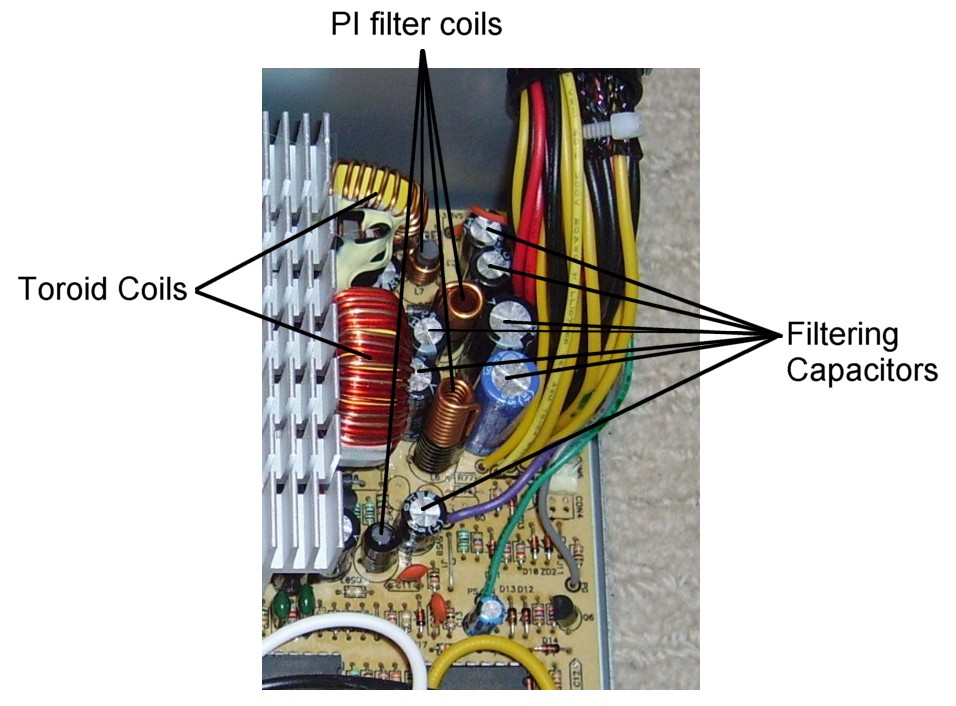
Finally we reach the output filtering. The caps for the three main rails are small (1000uF all around, the +3.3V and +5V caps should be 2200uF or more) and cheap, unreliable brands (good jap caps cost more pennies):

There is not a single PI coil on sight (copper costs pennies). The +12V rail is particularly bad here, it should have a filtering ouput with two caps flanking one PI inductor:

Instead there is no PI coil and only one single, small cap on this rail. That guarantees that +12V ripple will be beyond the roof and out of ATX spec. This murders HDDs, amongst other nasty effects.
Now if you don't mind we need the last pieces of info to complete the vivisection 😁 . Keep up the great work and please read and post here what is written on the three transistors attached to the primary heatsink, and also on the three rectifier diodes attached to the secondary heatsink. They are all like small black boxes with three metal legs, here is an example from another PSU:


With this info we will know what power this PSU can really deliver on each rail and overall.