Reply 60 of 265, by Fagear
- Rank
- Member
Can I jump in? 😀
I can draw PCB for the replica (as I did for SSI-2001 replica). I need at least two photos of both sides.
Can I jump in? 😀
I can draw PCB for the replica (as I did for SSI-2001 replica). I need at least two photos of both sides.
wrote:Can I jump in? 😀
I can draw PCB for the replica (as I did for SSI-2001 replica). I need at least two photos of both sides.
I think everybody would love your contribution. Yvan is a bit busy with a lot of projects so we would need someone as experienced as you are. You did an amazing job with the Innovation SSI replica so i think you would be a great engineer for this project too. Your help would at least save Yvan a lot of time as he mentioned that he needs to figure out what the GAL chip is doing.
wrote:
Hmm some of the traces go from the GAL16V8 to that set of jumpers. Has that set of jumpers got anything to do with the joystick port configuration?
I'll try and post photos over the weekend, along with the relevant pages of the programmer manual about jumper settings.
wrote:I'll try and post photos over the weekend, along with the relevant pages of the programmer manual about jumper settings.
Thanks Yvan that would be deeply appreciated. That way you could focus on trying to figure out what the GAL is doing and we can be sure that Fagear will do an excellent job drawing the PCB. This is a huge step forward in making this project a reality!!
Hello everyone,
sorry for the lack of updates, lots of things happening on my end. I did receive the ICs from Vetz, thank you again.
I will try and find time to take close-up photos of the Sound Master next weekend, I got an old iPhone 4 as a gift a few weeks ago, the camera is much better on this model. I'll try and take photos of both sides with and without light on the opposite side of the board, to better see where the connections go.
I use OsmondCocoa on my end to make PCBs although I don't quite understand how to go from schematic to traces yet, I usually just draw the traces manually for simple circuits. 😊
I didn' noticed you had made a post here Yvan.
I wanna thank you for keeping us updated and not giving up on this project. I'm also glad Fagear is willing to step up and help us, he is extremely productive and has been doing an amazing job on the Innovation SSI 2001 replica.
Alright, here's close-up photos taken with an old iPhone 3GS. I'll take better photos with an iPhone 4 if needed and if I have time, but it probably won't be until next week-end at best.
If someone can draw a crude representation of the card and its components I'll be happy to label them if I can (measure resistor values, read capacitor values, etc).
edit: It seems I can't attach a ~80MB zip file to my message, so I have upload the photos to my website instead.
The URL for the archive is http://www.yvan256.net/soundcards/Covox-Sound … er-1-photos.zip
That archieve is damaged!
~ At least it can do black and white~
wrote:That archive is damaged!
Maybe you've downloaded it before it was completely uploaded? The size is 82 148 706 bytes.
I've downloaded the archive, opened fine.
I will take a look at photos next day.
Awsome!!!
Thanks Yvan. The traces on the card are quite visible so the pictures are not too bad. But i'm a bit worried about that GAL.
wrote:I've downloaded the archive, opened fine.
I will take a look at photos next day.
If you need better close-ups on some area or parts details, just tell me.
wrote:Awsome!!!
Thanks Yvan. The traces on the card are quite visible so the pictures are not too bad. But i'm a bit worried about that GAL.
One step at a time. ..
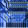
I took a look at how the joystick ports are wired, and I am puzzled. On the underside of the PCB, I see that pins 1-5 and 9 of each DE-9 connector are connected to the 74HC365 line drivers. Pin 8 seems to be the common ground pin, as one trace goes to the pin of each connector. I understood that these joystick ports were supposed to be Atari compatible, but standard Atari sticks use pin 6 for the first button input, which appears unconnected on this Covox. Each '365 provides six drivers, which would leave no room for pin 6.
Did Covox screw up here? A Master System controller would have a button on pin 9, but everyone knows how popular that system was in the U.S. A Sega Genesis controller should never be used with these ports because it needs pin 5 as +5v, not an input. Perhaps the joystick was meant only for directionals.
http://nerdlypleasures.blogspot.com/ - Nerdly Pleasures - My Retro Gaming, Computing & Tech Blog
I've started to laying out "replica" PCB. Let's see where I can get.
Thank you for your efforts Fagear. When i thought about a Covox Sound Master replica and i decided on launching this thread i only had a mere hope and never imagined we would progress so fast.
Special thanks to Yvan for being very helpful and alowing us to replicate his "specimen". Also i have to thank Jim "Trixter" Leonard to Yvan and Vetz for ordering AY-3-8930 chips. Everybody can make a difference. This is extremely cool.
Finished for today with it.
Feels like this board was auto routed. Traces are all over the place. No any logic comes through it.
Many traces are invisible under chips.
But still, I'll finish with what I have right now.
Currently using outline from SSI-2001 replica project. 😀
wrote:Finished for today with it.
[...]
Currently using outline from SSI-2001 replica project. 😀
Yeah, yeah, I can take a hint...
(viewed from components side)
What worries me about that GAL is the non-fab, white silkscreen on it that says "VDMA 1.3"
It is a bit difficult to find info, but some sources say the Sound Master has a DAC and it supports DMA for the DAC, so the PAL chip would be handling DMA protocol. Now, I can't find any timebase chip to trigger DMA transactions, so you guys with the schematics can re-post it or figure out if the sampling rate is fixed or somehow selectable.