VOGONS


First post, by ElBrunzy

User metadata
Rank Oldbie
Rank
Oldbie

I've seen some success story about people repairing hardware here, so I will try my luck.

What append is that I did try to upgrade the kickstart rom of an amiga1200, but when I installed the rom, some pins got bent. Resulting in an amiga that dont boot. So I removed the 3.1 rom and put back the 3.0 but I got only weird visual noise on the screen, at best I got a colored screen but I'm not sure what color it was exactly, didnt pay much attention as I did not know it was an error code. So I solder the kickstart pins that where broken and make sure to have a signal on each pins by checking them with a multimeter.

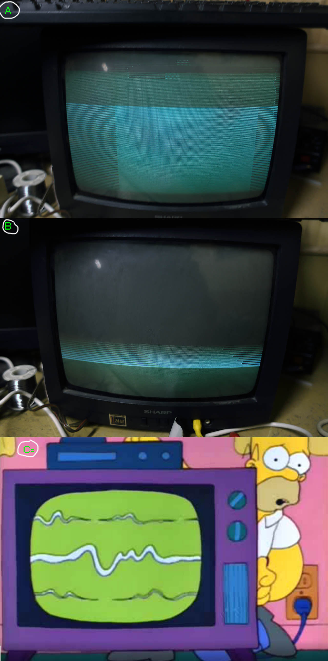
When I plugged it in, the power led of the amiga turn on and the hdd light blink to the hdd init activity, but I guess it could be somewhat just a simple link. I never was able to make seek or read a floppy. I took a picture of the screen using the RCA video out of the amiga. Using the RF out did give only snow (different from when the amiga was on/off, also did check channel 3/4 switch on the amiga), I used a 75-300 with it, was it a good idea?
amiga_1200_output.jpg
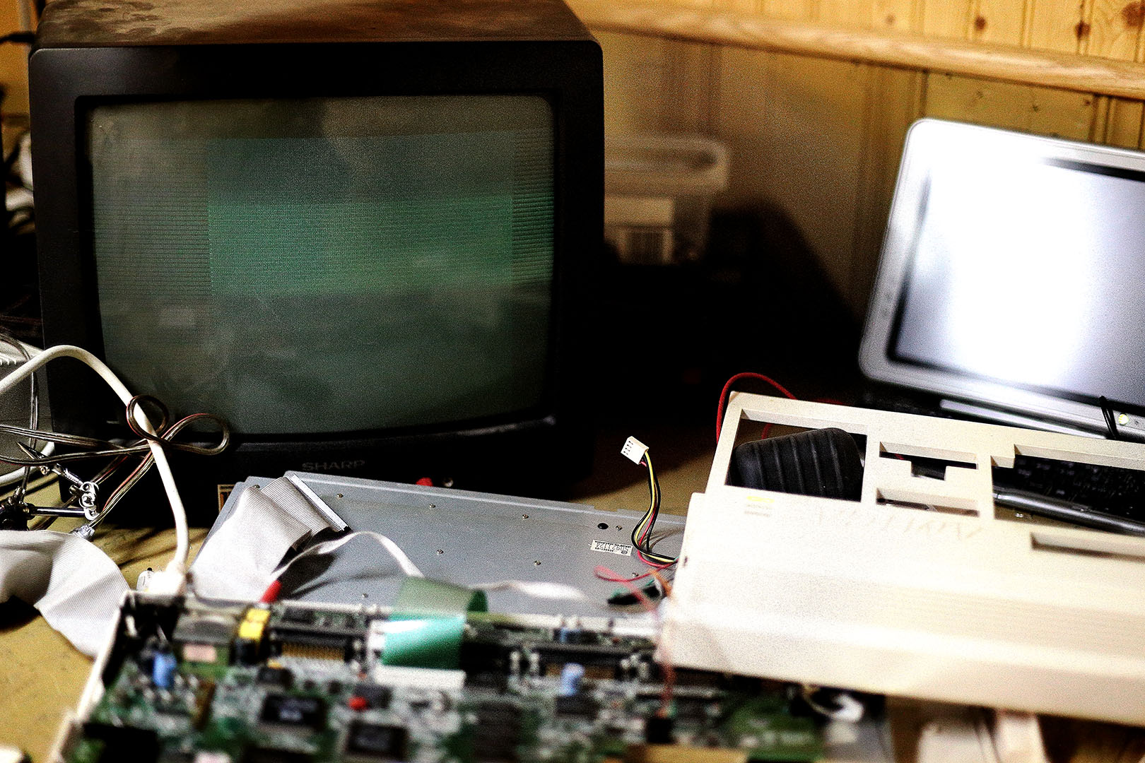
The screen seem to scroll up and the line you see are adjusted like if the image has bad field order sync.

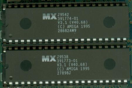
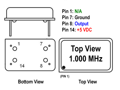
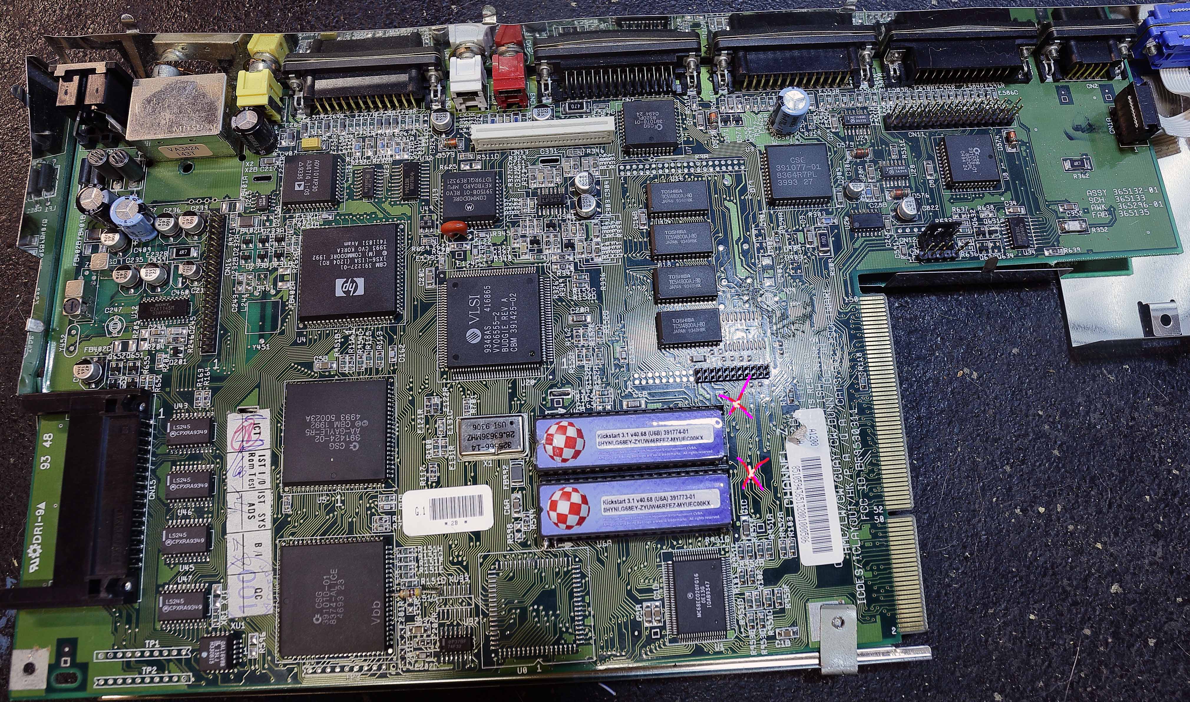
I did try to take a picture of the pcboard, you can notice the 28.63636 quartz his dented, I kicked it while trying to change the roms as they where very hard to remove. Maybe that is what is at fault ? I dont know how to test a quartz, I have HZ test in my ideal 61-361 multimeter, maybe I'll look at how to do it tomorrow.
aimga1200ntsc.jpg

I never was able to reproduce the color code with the 3.1 KS and I just dont find my 3.0 roms handy. But if it was a rom problem aint the screen would turn red as indicated here?

Of course I'm quite desperate about the situation. I cannot believe a bad rom swap would totally break an amiga1200. The bottom CSG 39-1010-01 and the MCE68EC get a little bit hot, but the other chips are rather cold. I dont really know the amiga so I have no real clue about what to look at, any help would be much appreciated. I was happy to have a small chance to experiment the infamous amiga, made it join my lan via ftp, listen to some mod on octamed and watched a demo or two, so at last I can check that on my bucket list 😵

Reply 1 of 9, by Jo22

User metadata
Rank l33t++
Rank
l33t++

Well, I'd love to help you, but I only was an A500 owner many years ago. I used the on-board VBS video and never had it working in colour.
But from what I can see, it seems your xtal oscillator is also damaged (28.63636 MHz). Luckily, it can be easily replaced if you find one.

If found several of them at Farnell Electronics. I'm not sure, but I think you need the 4pin/5v version (full oscillator).
However, I'm not sure if that's really the culprit here. It's just an idea.. And I reponsed, because no one else has done this so far..

Aren't there any real Amiga users around ?

"Time, it seems, doesn't flow. For some it's fast, for some it's slow.
In what to one race is no time at all, another race can rise and fall..." - The Minstrel

//My video channel//

Reply 2 of 9, by keropi

User metadata
Rank l33t++
Rank
l33t++

It's not clear from the picture, but the insulation layer is present between the mobo and the metal shield, right?
It's normal for the ICs you mention to get hot, so no worries there. I suggest you make this thread over at AmiBay so you can get better troubleshooting instructions as there are some very knowledgeable people there 😀

The only thing I can think of is maybe you damage a trace at the kickstart area (maybe a tool fell off?) or that the board bend lots so there is a solder crack somewhere ? I can't think of anything else killing a machine like that

🎵 🎧 MK1869, PCMIDI MPU , OrpheusII , Action Rewind , Megacard and 🎶GoldLib soundcard website

Reply 3 of 9, by Roman78

User metadata
Rank Member
Rank
Member

Or post at www.A1k.org. It's a german Amiga forum but there is an International Section.

Reply 4 of 9, by orcish75

User metadata
Rank Member
Rank
Member

Your kickstart roms have not been inserted properly. The roms have to be moved one pin to the right, i.e. the flat edge of the rom (right hand side of the rom in this picture) has to align with the flat edge of the rom socket. The small notch on the rom socket (left hand side in this picture) has to have one pin exposed on the top and bottom. See this pic.

roms31.jpg

Reply 5 of 9, by Jo22

User metadata
Rank l33t++
Rank
l33t++
orcish75 wrote:

See this pic.

"Amiga 1995" ? Yikes, a zombie! Run, people, run! 🤣

"Time, it seems, doesn't flow. For some it's fast, for some it's slow.
In what to one race is no time at all, another race can rise and fall..." - The Minstrel

//My video channel//

Reply 6 of 9, by ElBrunzy

User metadata
Rank Oldbie
Rank
Oldbie
orcish75 wrote:

See this pic.

Damn I feel stupid, I've checked many times to make sure they where alright, dont know why I got it wrong 😦
Nevertheless if I plug them alright I got the same result. In fact the a1200 behave exactly the same if there is KS rom or not in it. I've searched everywhere to find the old ks 3.0 but like everything I safely put aside, I dont find them when the times come that I need them back. At this point I'm losing hope to find the 3.0 roms at all as I search everywhere for 2 days. I think I remember here someone who announced in his signature he could mail some KS to active poster, I was hoping to grab his attention, or maybe I'm just not active enough 😁 There is some amiga fan in my city, so maybe I could find some here too. I've pay the high price for those KS 3.1 and prefer to check with spair roms if the a1200 is okay before I buy some others.

Thank Jo22, my multimeter can check the HZ and kHZ frequency, but I havent found the pinout of the crystal to check it. Do you know how to find the pinout of it ? I've did some research and try different possible combination of the pinout but never was able to make the multimeter show something that is near 28.63636. I dont know how it's done on the interior so I cannot tell if a small dent like this could be fatal to the piece. I'll make a stop to the electronic part store tomorrow.

Keropi / Roman78: Yeah good idea, I'll post to amibay and A1k, I'm really looking forward to repair that computer. About the traces, I've inspected them very closely and I can only see one that might look a bit suspicious, but I tested it and it's ok.

Reply 7 of 9, by Jo22

User metadata
Rank l33t++
Rank
l33t++
ElBrunzy wrote:

Thank Jo22, my multimeter can check the HZ and kHZ frequency, but I havent found the pinout of the crystal to check it. Do you know how to find the pinout of it ? I've did some research and try different possible combination of the pinout but never was able to make the multimeter show something that is near 28.63636. I dont know how it's done on the interior so I cannot tell if a small dent like this could be fatal to the piece. I'll make a stop to the electronic part store tomorrow.

You're welcome! 😀

The normal (classic) TTL-style oscillators are like this:

Q300-sch-pinout-420x315.jpg
How to test
Just remove it, add 5v to it, solder a small piece of wire to pin 8 (ouput) and tune a shortwave radio to this frequency.
It could be that the tone might not be exactly on that frequency, but a bit below or above.
It works best if your radio is SSB capable. If not, you will at least hear some noise or a crack sound.
Check if you hear something and make sure if the noise is stable (same sound).
If you can't desolder the IC, just hold the radio's external SW antenna next to it.
Sorry, that's all I can advise when someone has to use kitchen tools. 😉

Normally, someone would use an oscillograph, a frequency counter or a logic analyser.
Or just a dip meter.

The modern oscillators are in SMD form factor (strictly speaking, the normal is too):

S1614B-pinout.jpg

I havent't used them, though, so please be careful. They use 3.3v, because that's the new standard in micro electronics.
Speaking under correction, but I think they still can handle 5v in pratice.
- The older 5v types had their problems to correctly oscillate at a lower voltage like 3.3v..
To use the new ones as a drop-in replacement, you may have to mask pin 1 (use nail varnish, etc.).

But really, these are just my thoughts - better ask someone else who knows. 😅
The person in the electronics store can perhaps help you with this.
And if you decide to remove the old oscillator, install a socket instead (like in old 386 mobos).
So you can test different types, make adapters, etc.

@orcish75 Sorry about the joke above, but I couldn't resist. 😉

"Time, it seems, doesn't flow. For some it's fast, for some it's slow.
In what to one race is no time at all, another race can rise and fall..." - The Minstrel

//My video channel//

Reply 8 of 9, by orcish75

User metadata
Rank Member
Rank
Member

@orcish75 Sorry about the joke above, but I couldn't resist. 😉

Ha ha! No worries mate! Vogons wouldn't be the same if nobody had a sense of humour. 😀

@ElBrunzy

Take the mobo out of the metal shielding and retest, there might be a short due to the shielding.

As Jo22 pointed out, that xtal looks pretty beaten up and needs replacing.

I'm assuming the Amiga was working fine up until you changed the roms to the 3.1 version.

If you don't come right here, you can also post on http://www.amiga.org and eab.abime.net A few of the guys on those forums do Amiga repairs and might be able to help you.

Reply 9 of 9, by ElBrunzy

User metadata
Rank Oldbie
Rank
Oldbie

Many thanks Jo22 and orcish75 for the follow up.

I did some research about xtal metal can crystal generator. I understand that the inside pieces can be somewhat fragile so with the information you gave me and internet research I headed out to some electronic parts stores. I think I found a store that could have a provider who could have this piece, so I'm awaiting return. I did read that to test a crystal live would also disable it, and this could explain that I got deceiving lectures on the multi-meter before getting a total loss of signal. Anyway if I can get those pieces cheap it would be less bothersome than to test them. Thanks for confirming me that it's next to impossible to check a crystal with my so called kitchen tools 😒

I made the extra mile to take the mobo totally out of the metal shield. But it was no use. I guess now I dont have this bent metal to bother me all the time.

I was able to get some sign of life from the amiga if disconnect the hdd and plug only a emergency repair floppy. I will try to describe it with thoses screenshot :

  1. At boot up I always see this strange pattern that scroll quite fast at the top of the screen and then the screen is just like the ordered lines.
  2. Then the screen turn black and I can hear the floppy read something on the disk and after a while the floppy stop reading and this new pattern appear on screen
  3. This is exactly how I feel right now

amiga_freegames.jpg
I wanted to reproduce that with and without the ks rom to see if they matter in the process but I could not even reproduce this with the ks rom in place, I'm getting a bit discouraged. I think I will put it all together and post it on the amiga forum that I got suggested all along this thread.