VOGONS


Success repairing 286 battery leak

Topic actions

First post, by Malvineous

User metadata
Rank Oldbie
Rank
Oldbie

Hi all,

For anyone who's interested, I've just had some success repairing an old Headland HT12/A 286 motherboard which suffered from a barrel battery leak many years ago.

repair286-t1-before.jpg

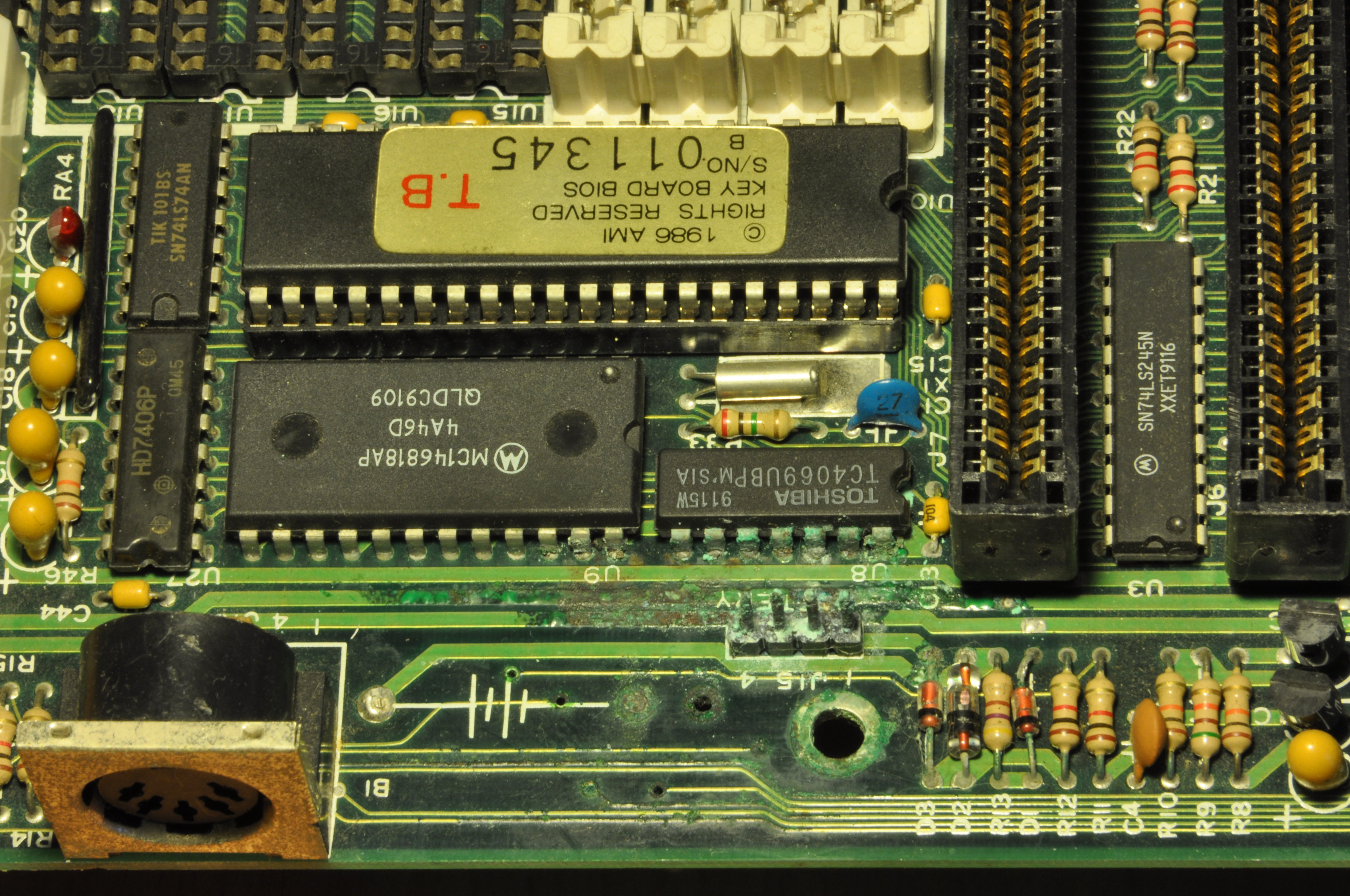
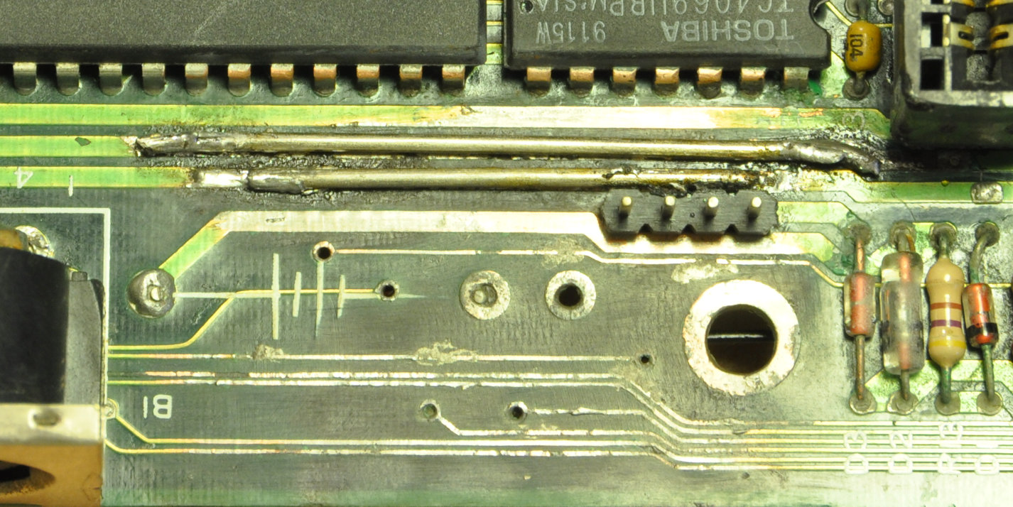
As it turns out, the only problem was that a few of the PCB traces had been eaten away. After cleaning off as much corrosion as I could, I could see the gaps in the tracks:

repair286-t2-cleaned.jpg

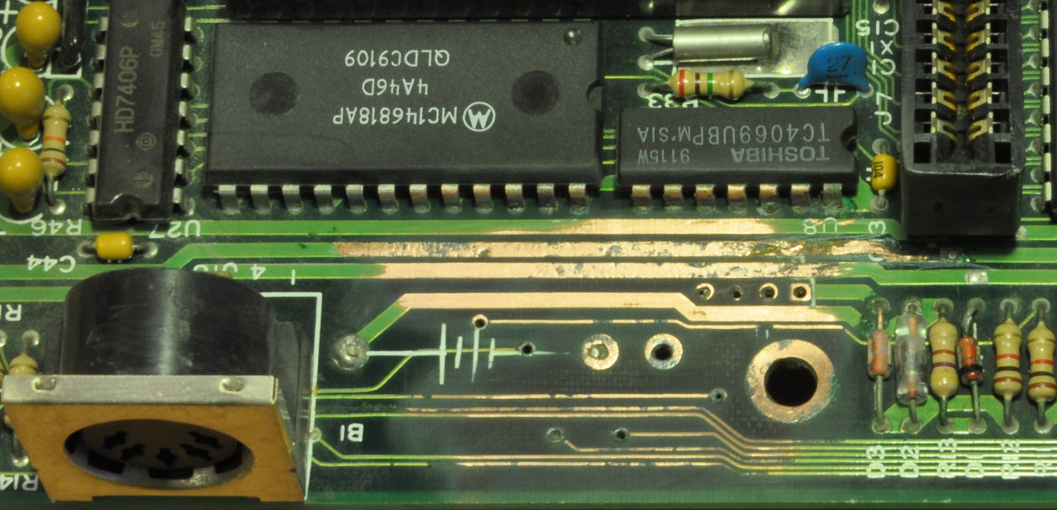
I tinned all the traces and soldered some wire directly onto the PCB traces that were carrying power. The small signal traces were unfortunately too small to solder anything to, and were too thin for a conductive pen to work (I tried using sticky tape to mask off the area and successfully got a line drawn of the correct size, but there wasn't enough conductive fluid to make a low-resistance connection.) Applying power got a POST card to show 01 but that was it - no beeps, nothing.

repair286-t3-tinned.jpg

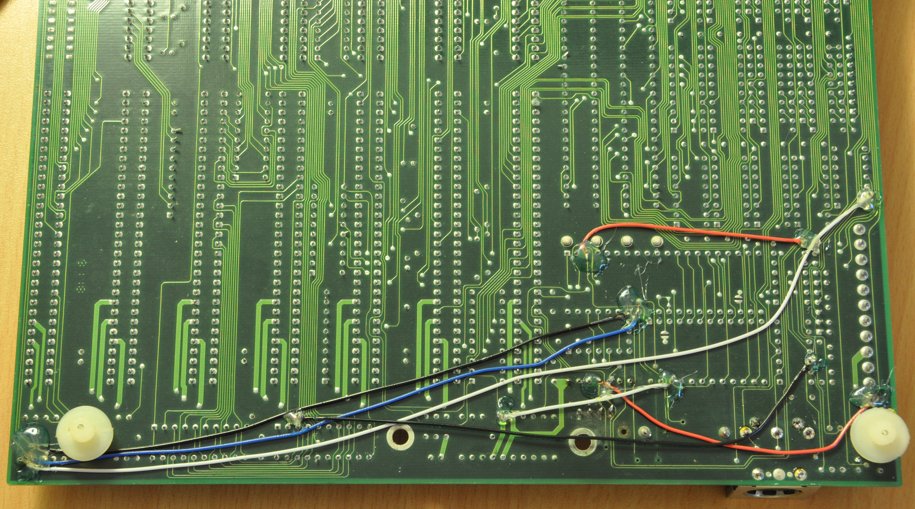
In the end I realised why am I trying to redraw the PCB tracks, when I could just find where they go and bridge either end with some wire. Not the neatest solution but certainly the easiest. This didn't work initially - the POST card got from 01 to 03, but still no beeps. I had to desolder and remove the keyboard connector to discover that a couple of the tracks changed direction underneath it - sneaky! That discovery involved moving one of the wires and adding a new one.

repair286-t4-back.jpg

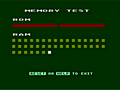
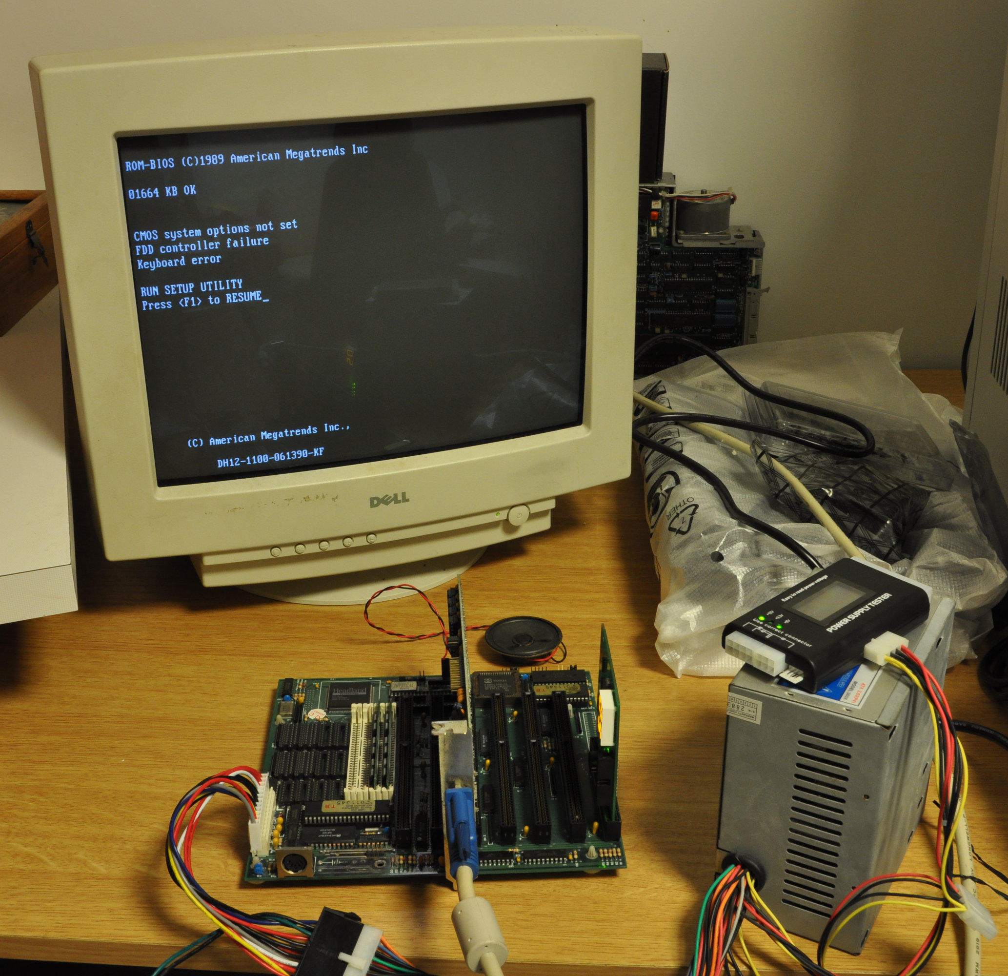
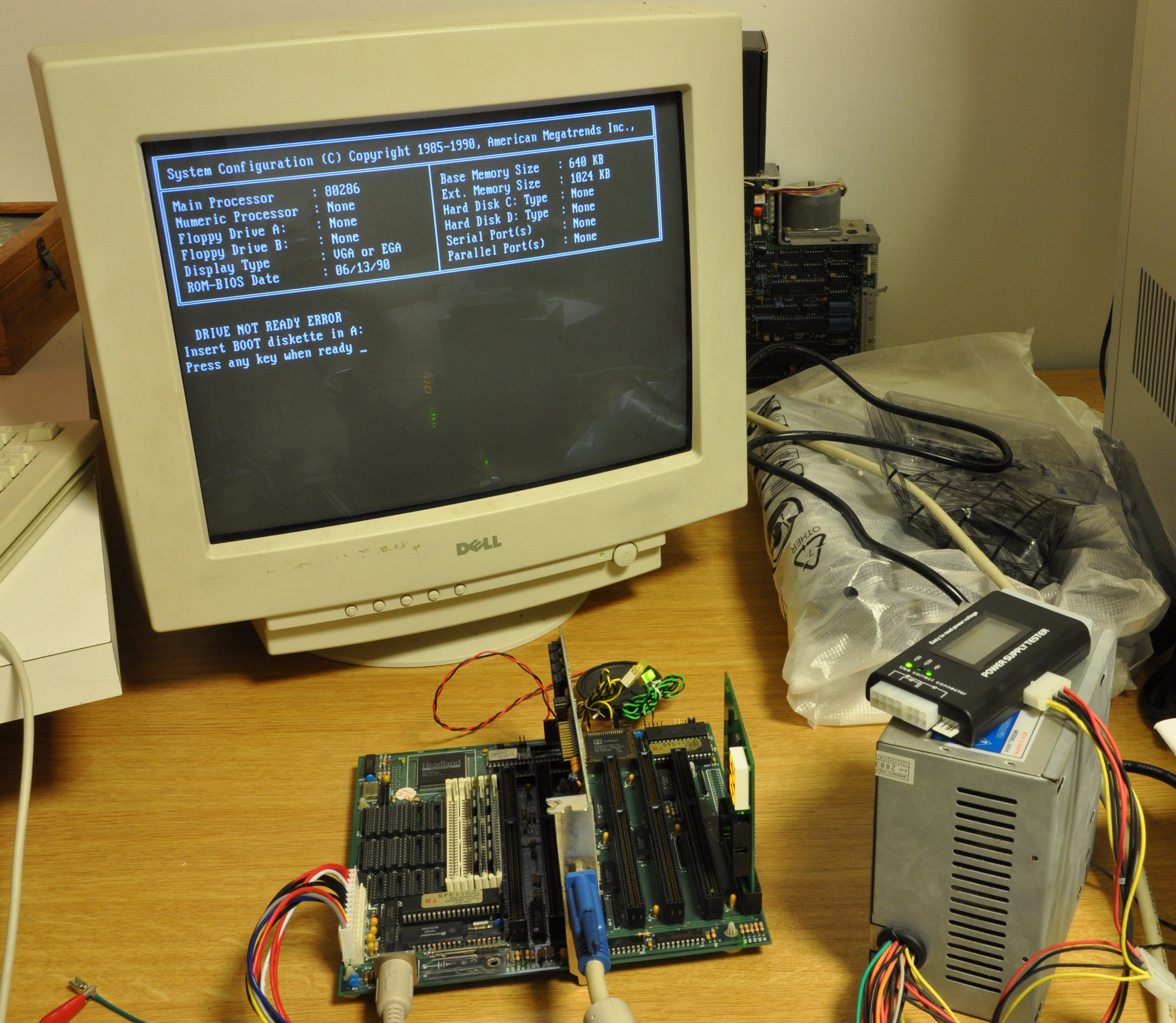
Powering the board now gave me sound! Two high-pitched beeps followed by eight lower-pitched ones, and then an odd series of clicks. The post card then settled on 74. Looking up code 74 told me "Display SETUP prompt" which then made me realise the odd series of clicks would have been the memory test running! Looking up the beep codes, two beeps is a memory parity error and eight beeps is a video card error. As I was using unknown memory, it could well be bad. But I grabbed an ISA VGA card to see if I could get a picture, and all the beeps went away! So I'm not sure what the significance of the two high-pitched beeps is.

repair286-t5-memcheck.jpg repair286-t6-cmos_setup.jpg repair286-t7-boot.jpg

Since this motherboard was originally purchased new, I still have the original manual for it. According to that, the battery connector takes +6VDC so looks like there will be no problems powering it from AAs. (Side note - is it worth scanning the manual in?)

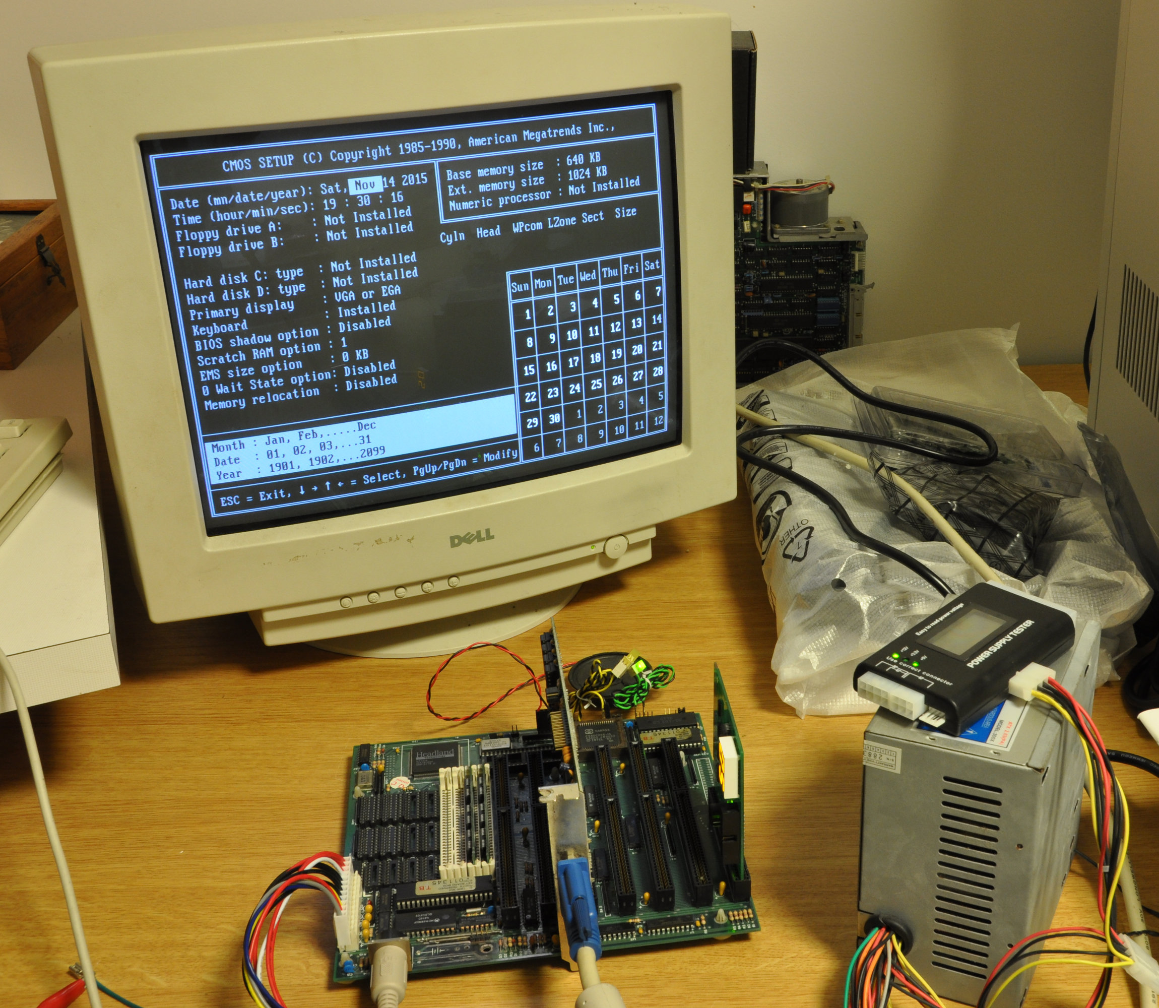
I'm curious how the memory works in this machine too. The memory check is always 384kB short, even when all the shadow options are disabled. There is an EMS option which appears to reduce the extended memory size by the chosen amount and provide it via EMS, but you never seem to recover any of that 384kB. Is this just the way the BIOS reports the memory values, or is it really making memory appear in the UMB and it is being "lost" by any option ROMs in the same space? If so it would seem to perform at the chipset level what EMM386 later did at the software level, which is interesting.

For those who like a bit of back story, this motherboard came from the second PC my family had, and back when I was a wee lad it died an untimely death. My father, being an electrician, had a poke around with the motherboard and concluded that the battery leak was too severe to attempt any form of repair. So the machine went back to the shop and we waited for the motherboard to be replaced.

When my father returned a week later to pick up the repaired PC, he asked for the old motherboard back. The technician in the shop didn't want to give it to him, but as my dad kept asking he finally went out the back and rummaged around for while, coming back with a broken 386 motherboard, which he said was even better than the 286 one so we should take that instead. My father took one look at it and said he didn't want that one because all the chips were missing. The technician started raising his voice to try to embarrass my father, asking why he would refuse a 386 in preference for an old 286, making sure everyone in the store's workshop could hear. Being my father, he just raised his voice even louder and said he wasn't going to be fobbed off and wanted his original board back, with all the chips on it he'd paid for. That seemed to send the message to the technician, who grabbed the original board from a nearby bench where it was waiting for the CPU and other chips to be harvested and resold.

The machine had 2MB of RAM, but we didn't get the SIMMs back. They weren't moved to the new motherboard either, which instead had no SIMM slots and only space for ICs. They had populated it with 2MB worth of ICs, and when my father queried the lack of SIMM slots, he was told this was the new way it was being done. My father didn't really believe this, but the machine worked and with no plans of upgrading, it didn't really matter. It's only looking back now that I can see they charged us for a brand new motherboard, but gave us an old second-hand one that probably someone else had had replaced during an upgrade, and the shop had obtained for free. Needless to say, we never went back to that store again.

For many years that broken motherboard sat in a cupboard, and eventually ended up in my collection of old computer bits. After reading all the discussions here about 286 machines, I decided to see whether I could resurrect it. I'm very pleased to have succeeded in that!

Reply 2 of 22, by Caluser2000

User metadata
Rank l33t
Rank
l33t

Good work. It's always nice to have a scanned manual for future ref. Not showing the reserved 384k is quite normal.

There's a glitch in the matrix.
A founding member of the 286 appreciation society.
Apparently 32-bit is dead and nobody likes P4s.
Of course, as always, I'm open to correction...😉

Reply 3 of 22, by 386_junkie

User metadata
Rank Oldbie
Rank
Oldbie

Excellent work!

That 'unrivalled' feeling you get... the moment you go to re-test a repair you've just attempted and the conditions change into a more functional state confirming a certain amount of success... is difficult to match or even beat. 😁

You've made me wanna go and dig out the soldering iron and repair something now! 🤣

Compaq Systempro; EISA Dual 386 ¦ Compaq Junkiepro; EISA Dual 386 ¦ ALR Powerpro; EISA Dual 386

EISA Graphic Cards ¦ EISA Graphic Card Benchmarks

Reply 5 of 22, by Malvineous

User metadata
Rank Oldbie
Rank
Oldbie

Thanks for the kind words! Yes there's a great deal of satisfaction returning something broken to working order. I've now put 4MB in the board (the max it will take) and I'm starting my adventure on how to boot it up from a more modern storage device (like a CF card.) Since I already had a Pentium by the time I was old enough to start learning about hardware, the idea of a BIOS that doesn't recognise IDE drives is very unusual to me! Time to see if I can get the XTIDE BIOS in there somehow 😀

The skills I ended up using are actually pretty basic - you just follow the damaged line in both directions until it reaches a solder point (metal part) and then join those two metal parts together with some wire. It's only time consuming because so many of those tiny lines together make you go cross eyed!

Reply 6 of 22, by stamasd

User metadata
Rank l33t
Rank
l33t

You can add XTIDE support with a card like this one: https://www.lo-tech.co.uk/wiki/ISA-ROM-Board

Even better, if you remove the BIOS chip and read its contents, and find that it has empty space at 0xF000, 0xF200 or 0xF400 you can make a composite BIOS image by adding the XTIDE code at one of the above addresses, then burn a new BIOS chip with the composite image. Code at one of the above addresses will be scanned during POST and initialized, this way you save both an ISA slot and a chunk of upper memory. 😀

I/O, I/O,
It's off to disk I go,
With a bit and a byte
And a read and a write,
I/O, I/O

Reply 7 of 22, by Malvineous

User metadata
Rank Oldbie
Rank
Oldbie

That's a good idea! I was going to use the bootrom socket on an ISA network card (although I do like the idea of the Lo-tech ROM board) but using spare space in the existing ROM is even better!

They are all (boot ROM + BIOS) 28-pin ROM sockets though, and I can only find 32-pin flash chips, like the Lo-tech board uses. From reading the datasheets it looks like you can use the 32-pin chips in a 28-pin socket if you connect a few of the extra pins together, however on the motherboard there are a couple of resistor packs in the way so this may be a bit tricky.

Can you still buy a new 28-pin flash ROM?

EDIT: No, but you can make a cheap adapter to fit a 32-pin ROM into the 28-pin socket.

Last edited by Malvineous on 2015-12-09, 12:08. Edited 1 time in total.

Reply 8 of 22, by chinny22

User metadata
Rank l33t++
Rank
l33t++

I'm impressed the board and manual lasted all these years even though you knew it didn't work.
Let the fun begin!

Reply 9 of 22, by BSA Starfire

User metadata
Rank Oldbie
Rank
Oldbie

glad you managed to save the board, well done!

286 20MHz,1MB RAM,Trident 8900B 1MB, Conner CFA-170A.SB 1350B
386SX 33MHz,ULSI 387,4MB Ram,OAK OTI077 1MB. Seagate ST1144A, MS WSS audio
Amstrad PC 9486i, DX/2 66, 16 MB RAM, Cirrus SVGA,Win 95,SB 16
Cyrix MII 333,128MB,SiS 6326 H0 rev,ESS 1869,Win ME

Reply 10 of 22, by Malvineous

User metadata
Rank Oldbie
Rank
Oldbie

Thanks guys!

I finally scanned the manual for the motherboard, and also the MFM controller that came with it, as I found that manual too:

Hopefully someone can upload them to Vogonsdrivers if they are useful.

I love the way the DTC BIOS didn't bother prompting the user to press a key to access the format utility during POST, but instead requires the end user to go into DEBUG and jump to the ROM code directly.

It's also intriguing they mention at the end of the motherboard user manual that there is a service manual also. I wonder whether anyone ever got hold of that?

Reply 11 of 22, by adalbert

User metadata
Rank Oldbie
Rank
Oldbie

I also managed to repair a 286 mainboard. I got it with some scrap parts and it was really dirty and the battery has leaked a bit.

dirty.jpg
Filename
dirty.jpg
File size
541.16 KiB
Views
4819 views
File license
Fair use/fair dealing exception

I neutralized the leaked substance with citric acid, then washed the whole board in distilled water. I fixed some traces (easy task) but unfortunately the mainboard didn't turn on.

near_battery.jpg
Filename
near_battery.jpg
File size
278.45 KiB
Views
4819 views
File license
Fair use/fair dealing exception

Then I noticed that someone (an amateur :p) probably was trying to remove the i286 12MHz CPU, but didn't know how to do it and the PLCC socket had some badly bent pins. I thought that there might be problem with contact between the CPU and the socket, so I decided to replace it with a new one. After I desoldered it, I noticed that traces underneath were damaged, probably with a screwdriver. Someone had to be trying trying really hard to remove the CPU... Fortunately, I only had to solder 4 wires to the nearby chipset, so it was also pretty easy task. I soldered new PLCC socket, put the CPU inside and it was time to check if it works.

desoldered.jpg
Filename
desoldered.jpg
File size
605.75 KiB
Views
4819 views
File license
Fair use/fair dealing exception
repaired1.jpg
Filename
repaired1.jpg
File size
436.22 KiB
Views
4819 views
File license
Fair use/fair dealing exception

You can see on the photo that I experimented with SIMM-30 sockets, but mainboard didn't want to accept 1MB modules. I populated RAM sockets with chips I removed earlier, unfortunately I only had 6 memory chips and 3 tag-ram? (i mean the smaller ones) chips, so I took 2 chips from a broken video card and I had now whole 1024 kilobytes of RAM, but there was one smaller chip missing.

I turned it on, and now it works! I get memory parity error because of that missing chip, but I will try to find a replacement. I never had a 286 computer so it's nice to have one now.

286_bios.jpg
Filename
286_bios.jpg
File size
130.79 KiB
Views
4819 views
File license
Fair use/fair dealing exception

But there is also another problem - i have no information about the manufacturer, model number or jumper settings for that mainboard. Can anyone identify that? Funny fact is that every component has very accurate markings on the PCB's description layer, there are even informations about exact resistance, capacitance or IC model numbers, but there are completely no informations about mainboard's manufacturer.

Repair/electronic stuff videos: https://www.youtube.com/c/adalbertfix
ISA Wi-fi + USB in T3200SXC: https://www.youtube.com/watch?v=WX30t3lYezs
GUI programming for Windows 3.11 (the easy way): https://www.youtube.com/watch?v=d6L272OApVg

Reply 12 of 22, by Malvineous

User metadata
Rank Oldbie
Rank
Oldbie

That's a pretty good job finding broken traces underneath the PLCC socket!! Have you checked TH99 for possible motherboard matches? It sounds like it could be a pretty generic board.

Reply 13 of 22, by PCBONEZ

User metadata
Rank Oldbie
Rank
Oldbie
adalbert wrote:

But there is also another problem - i have no information about the manufacturer, model number or jumper settings for that mainboard. Can anyone identify that? Funny fact is that every component has very accurate markings on the PCB's description layer, there are even informations about exact resistance, capacitance or IC model numbers, but there are completely no informations about mainboard's manufacturer.

Congrats! Nice job.

What is the BIOS string?

GRUMPY OLD FART - On Hiatus, sort'a
Mann-Made Global Warming. - We should be more concerned about the Intellectual Climate.
You can teach a man to fish and feed him for life, but if he can't handle sushi you must also teach him to cook.

Reply 15 of 22, by Jo22

User metadata
Rank l33t++
Rank
l33t++

Hi, sorry, not that for model - but I've found some generic HT12 manuals:
http://www.shikadi.net/files/vintage/ht12a_user_manual.pdf
ftp://ami.com/archive/Other_Manuals/!index.txt

The HT12 is also on Vogonswiki: http://www.vogonswiki.com/index.php/Headland_HT12
And in case you need the EMS driver, it can be found here: http://ibm-pc.org/drivers/memory/memory.htm

Good luck! 😀

"Time, it seems, doesn't flow. For some it's fast, for some it's slow.
In what to one race is no time at all, another race can rise and fall..." - The Minstrel

//My video channel//

Reply 17 of 22, by Jed118

User metadata
Rank Oldbie
Rank
Oldbie

Hello all,

I'm dealing with a similar issue - An AT board that I bought had a severe leak on it - I cleaned it up and replaced the battery, and it worked. For a few months.

Now it'll POST like usual, but there is a Keyboard Error. The Keyboard does light up its LEDS upon start, but I think there's no signal getting to the keyboard controller.

Does anyone know what the DIN pins connect to on the keyboard controller? I checked ground and VCC and that's fine. My guess is either the crystal traces that connect to pin 2 and 3 on a standard 8048 controller are shot, or the connection between the DIN pin 1 and 2 (CLK and DAT) are damaged. I unsoldered the DIN connector from the board and cleaned it up, resoldered it, and that did not help.

I'll experiment a little more using a working 386 board but for the time being, does anyone know where DIN pin 1 and 2 (CLK and DAT) go to on the keyboard controller?

Youtube channel- The Kombinator
What's for sale? my eBay!

Reply 18 of 22, by bjwil1991

User metadata
Rank l33t
Rank
l33t

The two beeps indicates 64k of RAM is bad, or BIOS settings went back to default since your board uses the AMI BIOS.

Discord: https://discord.gg/U5dJw7x
Systems from the Compaq Portable 1 to Ryzen 9 5950X
Twitch: https://twitch.tv/retropcuser

Reply 19 of 22, by DeafPK

User metadata
Rank Newbie
Rank
Newbie

Just wanted to say that I find these repaired 286 systems extremely pleasing. Makes me want to get my hands dirty with my Tandon 286 on the upper shelf, there.

*flies away*

"an occasional fart in their general direction would provide more than enough cooling" —PCBONEZ