VOGONS


First post, by greasemonkey90s

User metadata
Rank Member
Rank
Member

Anyone have a diagram for this particular switch. Currently reads 11 🤣. Trying to set it to 133.

Attachments

  • 20171113_234640-1.jpg
    Filename
    20171113_234640-1.jpg
    File size
    675.72 KiB
    Views
    1512 views
    File license
    Fair use/fair dealing exception
  • 20171113_234556.jpg
    Filename
    20171113_234556.jpg
    File size
    4.41 MiB
    Views
    1515 views
    File license
    Fair use/fair dealing exception

Reply 2 of 11, by bloodem

User metadata
Rank Oldbie
Rank
Oldbie

Sorry for the necropost, but if anyone managed to find and is willing to share a diagram for this Turbo display, I'd really appreciate it. 😀
For the life of me, I can't properly configure it (so far I only managed to set it to a static 133 MHz). What's more annoying, is that I didn't even find the turbo switch connector pins and I tried all possible combinations...
Searched for it here too, no clues for this particular display... It is somewhat comparable to SK-188, but much more complex.

1 x PLCC-68 / 2 x PGA132 / 5 x Skt 3 / 9 x Skt 7 / 12 x SS7 / 1 x Skt 8 / 14 x Slot 1 / 5 x Slot A
5 x Skt 370 / 8 x Skt A / 2 x Skt 478 / 2 x Skt 754 / 3 x Skt 939 / 7 x LGA775 / 1 x LGA1155
Current PC: Ryzen 7 5800X3D
Backup PC: Core i7 7700k

Reply 3 of 11, by bloodem

User metadata
Rank Oldbie
Rank
Oldbie

Managed to configure it like I wanted, but frankly, it was purely by mistake. I still haven't figured out WHY it now works.

Anyway, I'll just attach this photo, maybe it will help someone else in the future (the configuration is for 133 MHz Turbo / 33 MHz deturbo).

Attachments

  • 20210130_211727.jpg
    Filename
    20210130_211727.jpg
    File size
    1.41 MiB
    Views
    1225 views
    File license
    Fair use/fair dealing exception

1 x PLCC-68 / 2 x PGA132 / 5 x Skt 3 / 9 x Skt 7 / 12 x SS7 / 1 x Skt 8 / 14 x Slot 1 / 5 x Slot A
5 x Skt 370 / 8 x Skt A / 2 x Skt 478 / 2 x Skt 754 / 3 x Skt 939 / 7 x LGA775 / 1 x LGA1155
Current PC: Ryzen 7 5800X3D
Backup PC: Core i7 7700k

Reply 4 of 11, by Eep386

User metadata
Rank Member
Rank
Member

I have one of these as well. A diagram would be great if some kind soul ever finds and uploads one. 😭

For what it's worth though, whilst I was looking for the settings, I ran across this picture. Setting mine to match the jumpers in the picture, produces a static '266'.

download/file.php?mode=view&id=108556
(image procured from a Russian forum: https://www.drive2.ru/c/3015623/)

Attachments

  • T-398 266MHz.png
    Filename
    T-398 266MHz.png
    File size
    477.05 KiB
    Views
    1197 views
    File license
    Fair use/fair dealing exception

Life isn't long enough to re-enable every hidden option in every BIOS on every board... 🙁

Reply 5 of 11, by snufkin

User metadata
Rank Oldbie
Rank
Oldbie

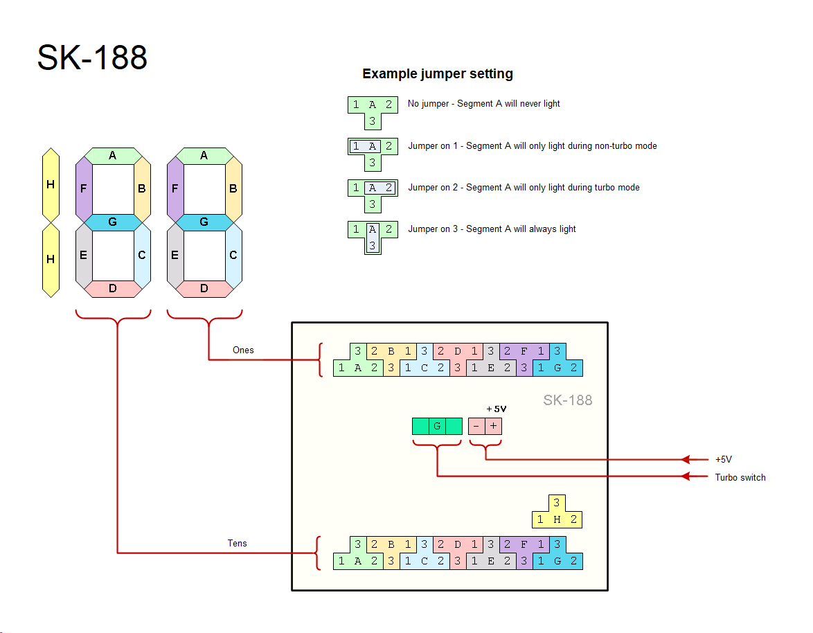
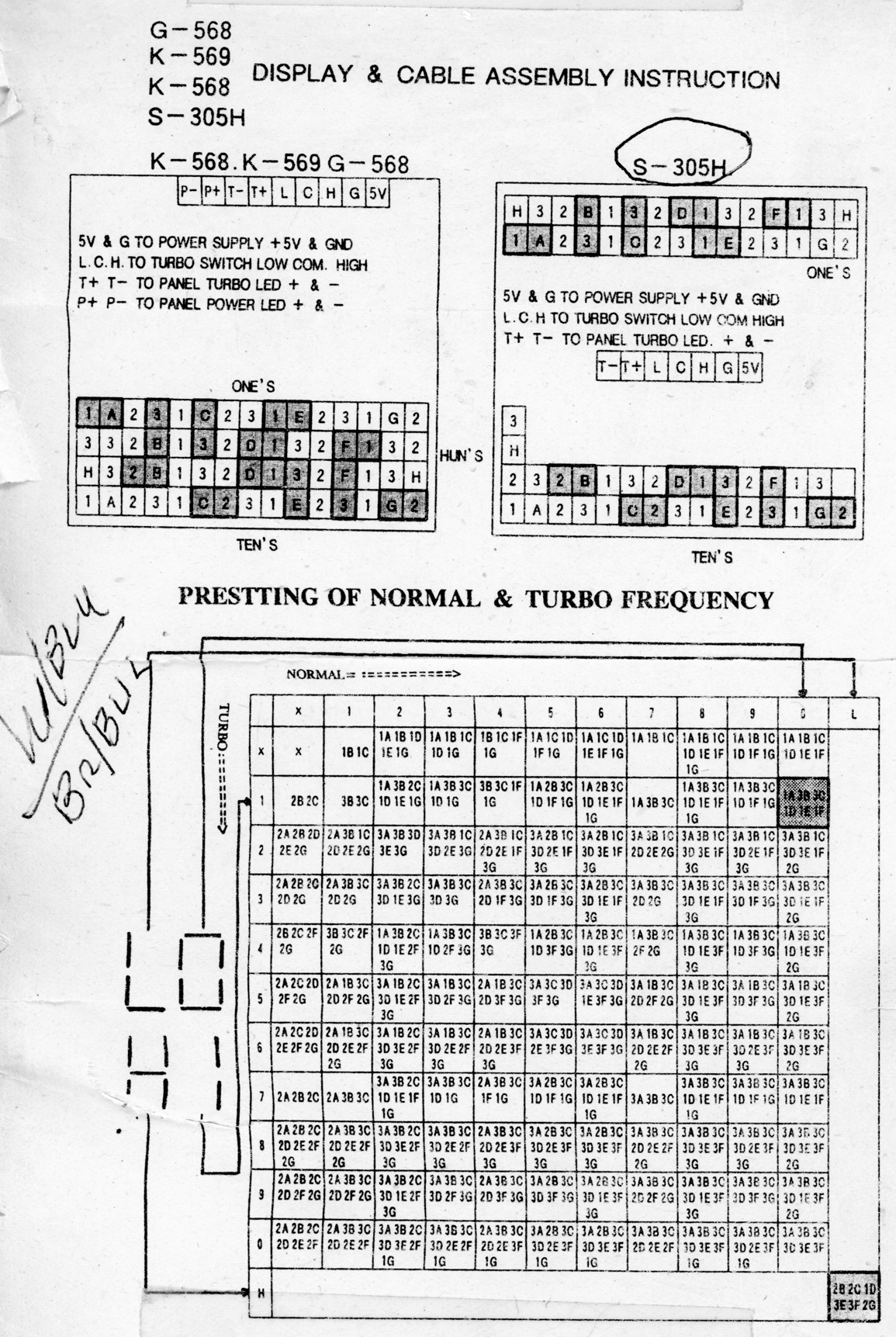
Looks like the PCB has markings under the jumper blocks that might show what controls what. If anyone wants to unsolder them all...

Or, and I'm Just speculating, but I can see markings for what looks like the +5 and Gnd pins around the top of the SE corner, and LCH (Low, Common, High?) in the centre block. Plus X, 10X and 100X, which I'd guess show which blocks control the units, tens and hundreds digits. Looks like the LED block has 22 pins, which I'd guess is 7*3+1 common. So, one of the +5 and Gnd probably goes to one end of the resistor, the other end goes to the C in the centre block, out to the switch, and back to either L or H. The other of +5 and Gnd probably goes to about 1/4 of the pins. Then 1/4 go to L and 1/4 go to H, from the turbo switch. The last quarter go to the pins to the LED module. If that's true, then once you know where they are it should make it possible to work out which pin lights up which display segment.

Based on that 188 display I made a guess about the layout, and it looks like it might line up with the other pictures you've posted. Rotating a jumper around the centre of each T sets the LED to either On-high, On-always, or On-low (or off always with no jumper). Maybe.

[edit: and of course I forgot the pictures...]

[top two rows are probably the Units, bottom two rows the Tens, row 3-9 the Hundreds. I'm least confident about the Hundreds]

Attachments

Reply 6 of 11, by AlaricD

User metadata
Rank Oldbie
Rank
Oldbie

I have this little buddy on an M-321 v2.7. I have it set so when the Turbo switch is on (latched in), it's in the high speed mode. The case Turbo LED is hooked up to the T-398, and is OFF when in high speed mode (button depressed) The display reads 40. When in "slow" mode (button OUT), the Turbo LED is lit and the display reads 33. I've marked the Ground and +V (it's about 1.97V) on a modified version of your pic, as well as drawn in jumpers for the settings so that Turbo on reads 40, and off reads 33.

I haven't metered the motherboard's own Turbo LED pins; if the output is too low to drive small CPU fan, I plan on using a transistor to turn on +5V power for a CPU fan-- so when Turbo is on the CPU fan comes on (and the Turbo LED itself goes out since it's hooked to the T-398).

I suppose I could adjust it so switch in = turbo, display =40, and LED is on, but the yellow light seems to be a better indicator of "slow" instead of "caution, it's TOO FAST!".

Attachments

  • t398.jpg
    Filename
    t398.jpg
    File size
    39 KiB
    Views
    1148 views
    File license
    Fair use/fair dealing exception

Reply 7 of 11, by snufkin

User metadata
Rank Oldbie
Rank
Oldbie

Thanks, I'd wondered about those extra pins, they had to be there for something (otherwise why got to the trouble of routeing traces to them and soldering in the pins) but forgot about a separate turbo LED. I'd guess that anything driving an LED will be current limited in some way (hence your 2V reading) to save burning the LED. Looks like on this display the current limit is that resistor. Only the one though, so I'd expect the LEDs to get a little dimmer the more that are lit (and possibly burn out if only a few are lit). Any idea what the value of that resistor is (looks like it might be orange-white-black, so 39 ohms)?

It always seemed a bit odd calling it a turbo button. That sounds like something that should only be used for short periods, rather than something that was left on nearly all the time, except for running games that ran too fast. I guess marketing didn't want to call it the slow button. So having the light remind you that you're in slow mode makes sense. Like a handbrake/parking brake warning light.

Reply 8 of 11, by AlaricD

User metadata
Rank Oldbie
Rank
Oldbie
snufkin wrote on 2021-05-01, 08:53:

It always seemed a bit odd calling it a turbo button. That sounds like something that should only be used for short periods, rather than something that was left on nearly all the time, except for running games that ran too fast. I guess marketing didn't want to call it the slow button. So having the light remind you that you're in slow mode makes sense. Like a handbrake/parking brake warning light.

Calling it "Turbo" when latching it in slowed the computer and turned on a yellow light is the dumbest thing ever.

Reply 9 of 11, by Eep386

User metadata
Rank Member
Rank
Member

Thanks for the partial diagram! I'll be savin' the pictures. 😀

Life isn't long enough to re-enable every hidden option in every BIOS on every board... 🙁

Reply 10 of 11, by lnino

User metadata
Rank Newbie
Rank
Newbie

Hello guys,

I am building a retro pc right now and was searching for the turbo pins of my mainboard in the www.
After some picture searchings on google I ended up in this forum.
I have seen that you guys are searching for a manual of the T-398 display.

In my retro PC there was little sheet of paper cable tied to the AT power supply.
When I opened the tie and put the old paper pieces together I saw that it is the manual for the T-398

Have fun with it.

greetings from Austria

Attachments