gdjacobs wrote:Flashing a uC is generally a lot easier than building a moderately complex pcb. Certainly not the same skill set, but it's a handy and useful thing to know how to do when working in embedded, so not generally a stretch to ask for it.
It is? I have no idea how to flash a uC, or what kind of tools will be required.
Soldering some components onto a PCB, that I can do.
gdjacobs wrote:Hierophant mentioned the trick would be ensuring no output until it's time for playback. How is it done with an actual PCjr or Tandy, both on bootup and between Tandy aware titles running? The goal should be replicating that behavior, I would think.
PCjr and Tandy do not actually mute the output.
They just send the volume commands ASAP on powerup.
I agree that trying to replicate the volume commands is the goal. But that means that a mute circuit is not required.
And as explained before, having a mute circuit does not solve the need for sending these volume commands at some point.
The only reason why you would need a mute circuit is to keep the machine silent until you can send the commands, if you cannot send the commands immediately on powerup.
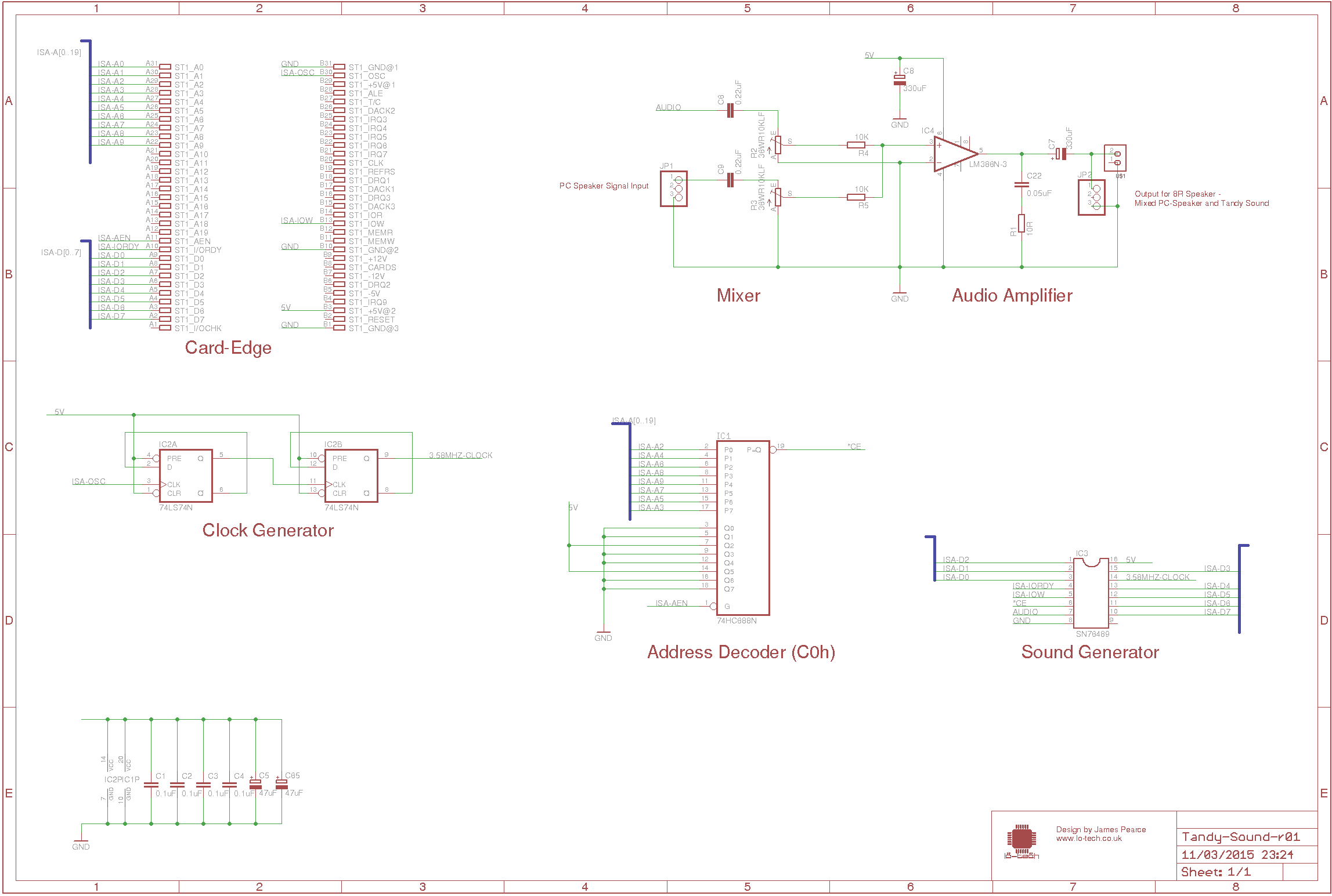
gdjacobs wrote:an improved Low-Tech card would certainly be great
I think a lot of people would like a lo-tech card, even the first revision.
But if a new batch of PCBs is to be made, I would suggest at least some small fixes, mainly fixing the circuit so we no longer need the two patch wires, and making the volume knob accessible externally. That way you could at least mute it manually. A 'kill switch' would also be nice, so you can leave the volume in the preferred position.
gdjacobs wrote:Implementing a state machine in bubblegum logic can get quite expensive, depending on the sequence required.
But as we already explained, the sequence is simply:
9F (10011111)
BF (10111111)
DF (11011111)
FF (11111111)
So as you can see, most bits are always 1 in this sequence, and only bits 6 and 7 count up linearly in this sequence. That is why the counter makes so much sense. It generates the sequence directly.
If you use a 4-bit adder, you could use the two most significant bits for the sequence, and bit 1 to toggle the CE and WR lines.
You can use the carry to shut the circuit off after the sequence has been completed (all the '1' bits could be generated by inverted carry perhaps... carry driving some and ports or whatever for muxing).
I think the circuit could be started by (!RESET AND CLK). That is, if I'm not mistaken, the RESET line is asserted for a short while on powerup. So you don't start counting until the RESET went low, to give the SN76496 some time to initialize itself before sending the commands.
Now, I don't have the engineering skills to make this into a complete circuit, but I think my suggestion got us 90% there already.


