VOGONS


First post, by user33331

User metadata
Rank Member
Rank
Member

Hello ( Bought a used graphic card )
Is it normal that MSI 6800 AGP-version(TD-128) misses a 4-5 pcs of SMD chips on the back ?
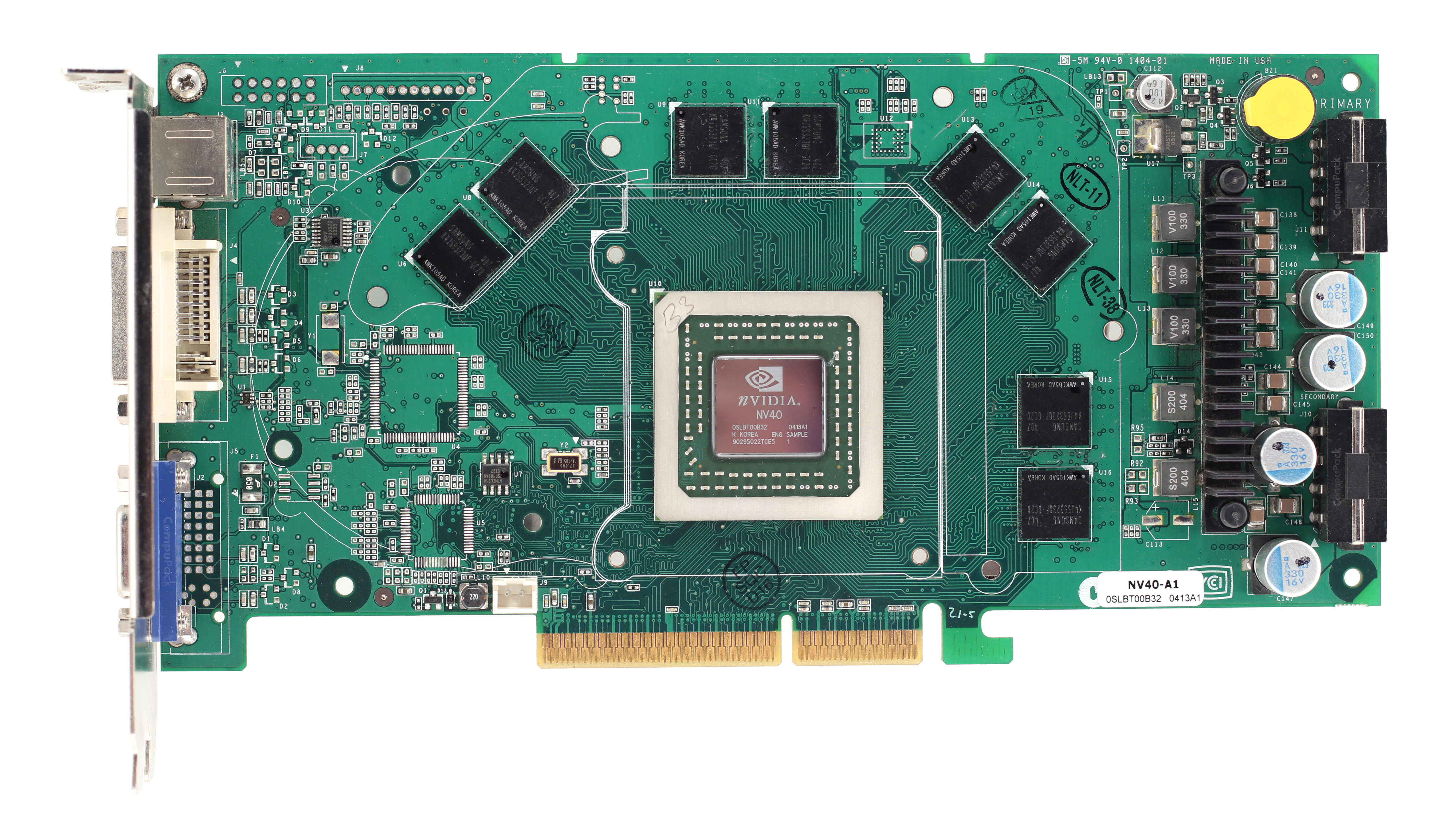
- I drew crude points *from my memory* on Geforce's reference card[photo] where the missing SMDs are.(Note: that photo attachment is a somewhat similar reference only and not from the card I own.)
- There are marks that solder is ripped of, leavings and clues that SMDs were there at some point.

- Is there a way to easily identify and buy these SMDs(ebay) ? Maybe use conductive glue to place the new ones without soldering.
- It is amazing to me how SMDs(max.5pcs) are missing from this card. It got to take some force/direct hit to remove these SMDs 🙁 Weird.
- What is the function of these SMDs on the back and could the card somehow work without them ? ( I haven't tried it ON because it might break the card for good. Without these missing resistors and such.)
+ Could someone post a picture of a same working MSI 6800 AGP TD-128 card(back side) so I could compare if it is missing the same SMDs too ? Like is this normal for MSI that the SMDs are taken off or... ?

  • One missing has a white code "C998" on side of it

- Is this some kind of "tuning" that people did in 2004 to get the card running faster ?
http://images.highspeedbackbone.net/skuimages … M452-7008-c.jpg

Reply 1 of 18, by Auzner

User metadata
Rank Member
Rank
Member

The board ran too hot or got mishandled. SMDs are easy to sheer off.

The components numbers are labeled on the silkscreen of the board. They start with a designator to indicate which type of part they are; "C" parts are for capacitor, "R" for resistor, "D" for diode. Without a schematic it will be tough to tell what value goes there without a duplicate card you can remove and measure parts from. Missing capacitors will cause more signal noise and possibly instability to the point the card won't run reliably. Missing resistors may break a connection or fail to pull down a value for circuit logic. Missing diodes may break a connection or remove a failsafe. There are smd solder technique videos on youtube, it takes some equipment.

One thing you can do is see where the two ends of each part go. It looks like that bigger SMD cap piece goes to the RAM. There are many like it on the board so you can desolder another cap and measure it off the board. Or try to find a datasheet for that memory chip and see if it has an example circuit and recommended capacitors. The missing bottom cap may be for filtering fan noise since it's near that header. The missing diode could possibly make the DVI-I port (analog or digital) not work properly if at all.

http://vgamuseum.ru/wp-content/gallery/nvidia … 00_agp_es_r.jpg
http://vgamuseum.ru/wp-content/gallery/nvidia … _agp_es_f_n.jpg (odd that there's a buzzer on this, engr sample silicon)
http://www.alldatasheet.com/datasheet-pdf/pdf … 323QF-GC20.html

Reply 2 of 18, by user33331

User metadata
Rank Member
Rank
Member

I have a buzzer too(round sticker on top of it). When the buzzer sound is activated ?
Without fixing the missing SMDs first could I possibly try the graphic card on to motherboard or will it make the card worse or even harm the motherboard ?

Reply 3 of 18, by Auzner

User metadata
Rank Member
Rank
Member

Perhaps the seller never noticed the missing parts and had it running like that. Did they sell it as a working card? If you think it's too big of a project you can still try it as-is and hope for the best.

Reply 4 of 18, by user33331

User metadata
Rank Member
Rank
Member

Hard to tell a female seller... The card is from around 2004. Speculations: the first user probably used it for max.2 years (at that time everyone left AGP to PCI-E ). I do not know the usage history and it is pretty awkward to ask for it...She had it for 10euro=10usd$ for "refunded if found unusable"-status and she refunded because of these missing SMDs.

She kept it in a bubble wrap and said no "mishandling happened" ( no antistatic bag or original package though might indicate she is not the 1st user )
- Don't know if she vacuumed those SMDs off or such.
- 14 years is a long time for things to happen in a regular household.

Reply 5 of 18, by Taijigamer

User metadata
Rank Newbie
Rank
Newbie

Do u have a clear pic of your graphics card? It takes a lot of force to shear off soldered smd unless the solder had failed. Some pcb revisions omitted certain components as they were not needed. Is there clear evidence that they were ever there in first place? The smd are caps in that picture. It shouldn't damage the card or board to try it, worst case scenario, it won't display a picture. Like Auzner said, it will be hard to find the cap values without a schematic of the card. If they need replacing, u will need to solder them, conductive glue won't do.

Reply 6 of 18, by Auzner

User metadata
Rank Member
Rank
Member

I'm very confident that nobody removed those SMDs as a "performance mod" of any sort. They all look to be filtering related. The biggest problem of those 3 would be the cap for the ram. If the ram is not stable you will get on screen glitches. The other two won't matter so much if your motherboard and power supply are high end components in regards to power design.

Find a way to remove C117 and measure its capacitance. Measure its dimensions in mm. Then order the SMD cap of the same dielectric (prob ceramic?), size (1206?), and capacitance (10pF?).

Reply 7 of 18, by user33331

User metadata
Rank Member
Rank
Member

I will send HI-res pictures today if I remember but what site hosts pictures today ? ( I haven't shared online pictures for a while. All my 30+ time goes now to 8h of work + 1h to drive back and forth to work. )
- 10 years ago photobucket.com was one but today it does not support "3rd party sharing of photos"-like forum sharing. + Many people say photobucket.com shows a lot of advertisements and such harmful things to viewers and boycott it.
- What is the suggested place to upload and share photos in 2018 that everybody likes ? Without bandwidths exceeding and accounts freezing.

Reply 8 of 18, by user33331

User metadata
Rank Member
Rank
Member

Here is the card MSI NX6800 basic model (Not GT, not Ultra):
- The card is TD128 AGP-version ( There exists TD256 PCI-E version )
Whole card:
https://imgur.com/OeK2MMO
Pinpointed missing SMDs: (Might be more)
https://imgur.com/LmFQTBN
Close ups:
https://imgur.com/kYvYZ7j
Front side:
https://imgur.com/SHNegtw

Reply 9 of 18, by Auzner

User metadata
Rank Member
Rank
Member

Definitely damaged. VGA output will probably be missing a color. All of that is going to be a lot of work. Pretty much time to find a new card. If you have storage it's worth hanging onto if you are a collector and one day get time to learn SMD rework.

Reply 10 of 18, by user33331

User metadata
Rank Member
Rank
Member

So the root cause to the missing SMDs is ? ( and how to avoid this myself in future so that this won't happen to my own precious cards )
1.) It was intentionally overclocked to extreme and overheated so that all the SMDs melted away when still in the PC ?
or
2.) This happens normally to all graphic cards just due to old age ? Long normal usage caused a worn out card.
or
3.) Someone used outside mechanical force to those chips ? ( Hand rubbing, vacuum cleaner, such...)
or
4.) Bad construction quality of MSI which lead to problems...Might have gone under warranty at that time 2004-05 perhaps ?

Reply 11 of 18, by Auzner

User metadata
Rank Member
Rank
Member

Usually overheating the parts fall off and would leave the solder pads intact. The damages in the photo looks like it was roughly handled or stored improperly. Cleaning wouldn't do that unless you were chipping off dried mud with a screw driver. Store it in its own anti-static bag before placing it in a box is good enough.

Reply 12 of 18, by Mr.Schnitzel

User metadata
Rank Newbie
Rank
Newbie
user33331 wrote on 2018-01-25, 14:49:

Here is the card MSI NX6800 basic model (Not GT, not Ultra):
- The card is TD128 AGP-version ( There exists TD256 PCI-E version )

Hi, sorry to dig this thread out of the basement! I stumbled upon a MSI 6800LE AGP with a blown MOSFET on Q509 (backside).

Could you share the exakt part number of that MOSFET. Since mine is melted, I‘m not able to identify the model number…

The board layout seems to be the exact same as your MSI.

Thank you so much!

Reply 13 of 18, by myne

User metadata
Rank l33t
Rank
l33t

Re: Quadro FX 3450 (geforce 6800) bad memory channel

Not the same board, but full schematic.

MSI schematics are fairly easy to find if you look around.

I built:
Convert old ASUS ASC boardviews to KICAD PCB!
Re: A comprehensive guide to install and play MechWarrior 2 on new versions on Windows.
Dos+Windows 3.11+tcp+vbe_svga auto-install iso template
Script to backup Win9x\ME drivers from a working install
Re: The thing no one asked for: KICAD 440bx reference schematic

Reply 14 of 18, by tehsiggi

User metadata
Rank Oldbie
Rank
Oldbie

Ahoy, the specs of the FET can be found in the schematic (not the high end! variant) from NVidia:

The attachment Screenshot 2026-06-26 at 12.50.50.png is no longer available

Now they didn't state any part number. Desired package is LFPAK, however Power SOP8 or something like that might fit as well, as in your picture.

I looked for some pictures of 6800 LE cards, found one where you can read the marking

The attachment Screenshot 2026-06-26 at 12.52.03.png is no longer available

2168 - it must be a single N-Channel FET - leads me to:
https://www.renesas.com/en/products/hat2168h/ … s/hat2168h-el-e - HAT2168H

Tough to get. I'll look for a replacement part.. - You can use this one, a good match and in production: PSMN7R5-30YLDX

myne wrote on 2026-06-26, 10:54:

Not the same board, but full schematic.

Does not seem match up. Q509 on his board is working together with Q504 and Q506 - in yours it's together with Q511, Q512, Q508.

AGP Card Real Power Consumption
AGP Power monitor - diagnostic hardware tool
Graphics card repair collection

Reply 15 of 18, by Mr.Schnitzel

User metadata
Rank Newbie
Rank
Newbie
tehsiggi wrote on 2026-06-26, 11:02:

Ahoy (...) You can use this one, a good match and in production: PSMN7R5-30YLDX

Thank you so much for your help! Do you think it's probably usefull to replace Q504 and Q506 as well? And what would you say which parts are generaly good replacing as a preventative maintenance? I could order and replace everything at once since I'm already "in there".

Reply 16 of 18, by tehsiggi

User metadata
Rank Oldbie
Rank
Oldbie

Q506 looks not too happy either. I'd change all three of them. While you're at it: Desolder them and check the rails resistance against ground. Just to make sure, it doesn't have a short. The highside fet being dead (Q509) is a tad bit dangerous, as it's short would send 12V straight to the GPU.

AGP Card Real Power Consumption
AGP Power monitor - diagnostic hardware tool
Graphics card repair collection

Reply 17 of 18, by Mr.Schnitzel

User metadata
Rank Newbie
Rank
Newbie
tehsiggi wrote on 2026-06-27, 11:00:

Q506 looks not too happy either(…)

Yes, that’s what I thought as well. What replacement chip would you recommend for Q504/506? Sorry for bothering, I‘m new to soldering myself and don’t want to make unnecessary mistakes!

And does it make sense to recap the board as well?

Reply 18 of 18, by tehsiggi

User metadata
Rank Oldbie
Rank
Oldbie

Sorry for the late answer. The FETs for Q504 and Q506 are IRF7032 - they are still available. Recap can be done at the same go. You could de-solder the caps and then measure ESR etc. and decide. Or you just order replacements and replace them right away. As long as you meet the voltage / capacitance / ESR rating you would be good.

AGP Card Real Power Consumption
AGP Power monitor - diagnostic hardware tool
Graphics card repair collection