VOGONS


First post, by w0lf42

User metadata
Rank Newbie
Rank
Newbie

In an attempt to clean up the wiring on my system, I'd like to change how everything is currently connected. My plan is to connect 2 x MIDI 5 Pin DIN Connectors (one for MIDI In and one for MIDI Out) and connect the SPDIF Out to the Audio Interface Bracket to the 40-pin header on my Creative Labs Sound Blaster Live! 5.1. The potential problem is that the Sound Blaster only has 2 x +5V Power Supply connections, but I need 3.

I got the idea to use the Audio Interface Bracket from PhilsComputerLab (A big thanks if you read this).

Can I:

  • Split one of the +5V Power Supply connections (from my Sound Blaster)
  • Use one of the +5V from a Molex connector (from my power supply)

diagram.soundblaster.2.png

diagram.midiconnector.2.png

diagram.interfacebracket.2.png

Reply 1 of 47, by Malvineous

User metadata
Rank Oldbie
Rank
Oldbie

5V is 5V so it generally doesn't matter where you get it from, except in special cases where there is a dedicated power supply for things like low noise/ripple/etc. But I don't think that's the case here.

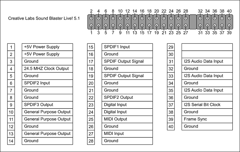
The real question is how much power is available from the 5V connectors, and how much do you need? What are you going to use the 5V for, and how much current does that use require? The Molex connector is going to have significantly more current available, so the SBLive's connector is only going to be for things that use very little power, like driving the opto-isolator LED in a physical MIDI connection. LEDs typically use around 20 mA, but probably less in this case, so it's possible the SBLive pins are only rated to supply a very small amount of current. If you use those connectors for MIDI you'll be fine, but you'll have to do some tests before you rely on using that 5V source for anything else.

The Molex connector is capable of delivering significantly more current, so there's no problem using that as well, just bear in mind that it can supply so much current and the connectors are so small, that any fault or short circuit may not shut off the power supply and could instead heat up the wires until they melt or the insulation catches fire. Having that much power available and trying to cram it down a tiny wire does not always end well 😀

If I were you I'd be tempted to bridge the two 5V connectors on the card (they are almost certainly bridged already, but you can test this with a multimeter in continuity mode to be sure) and then use the combined cable to power all three devices. If you plug in everything you plan to run on all three connectors at the same time and measure the voltage, you should see it remain right on 5V. If it starts to fall below 4.9V then you're drawing too much power and will have to disconnect and have a rethink.

Reply 2 of 47, by w0lf42

User metadata
Rank Newbie
Rank
Newbie

I've successfully bridged the two 5V connectors on the card. However, I discovered that the digital connection does not require the 5V. So, I've ended up not needing to do either option. But, thanks for the detailed response.

Reply 3 of 47, by NJRoadfan

User metadata
Rank Oldbie
Rank
Oldbie

Option #2 for MIDI is to use a DA-15 to MIDI breakout cable. The MIDI signals are still present on the joystick port of the Live! series cards. MIDI itself generally doesn't carry 5V, I would not wire it unless your device indeed needs it.

Reply 4 of 47, by w0lf42

User metadata
Rank Newbie
Rank
Newbie

For those who are interested, I've successfully created a 40-pin breakout connector/cable for my Sound Blaster Live card.

Here's the cable:
time.machine.40pin.audio.connector.png

And here's a diagram of all of my audio connections:
time.machine.audio.connections.png

Thanks again for all of the help.

I'll do my best to answer any questions.

Reply 5 of 47, by Intel486dx33

User metadata
Rank l33t
Rank
l33t

I know Philscomputerlab did a video about adding Toslink to the SB_Live card.
Also the Live drive breakout box that originally connects to the SB_Live card has a bunch of connections
So I think you can also use a live_drive breakout box with the SB_Live card too.
https://youtu.be/rVNSyRAwVXs

Also there is some adapters you can use instead of moding a 40-pin ribbon cable.
I like to use the adapters with Rasberry PI wires.
No soldering needed and easy to setup and trouble shoot.

Attachments

Last edited by Intel486dx33 on 2019-04-08, 07:41. Edited 1 time in total.

Reply 6 of 47, by w0lf42

User metadata
Rank Newbie
Rank
Newbie

I saw that video and initially used that idea. I ran out of PCI/ISA slots, so that isn't an option for me anymore.

Also, I was using those rainbow cables, but they get loose after a while and I had them disconnection from the 40-pin header. Also, I need to connect them to 3.5mm headphone/audio and RCA connections. So, technically, I could have done that without soldering, but this is cleaner solution for me. For a solder-free option, I completely agree with you. That just wasn't the solution I needed.

Reply 8 of 47, by Intel486dx33

User metadata
Rank l33t
Rank
l33t

I don’t understand what you are trying to achieve with this mod ?
What is it intended to do ?
Can you take a photo of the back of the computer too ?
What do you need these connection for ?

If you add a TOSLINK optical out connection you can connect your computer to an A/V receiver and have virtual 7.1 surround sound using Pro Logic setting. Or maybe even Dolby Digital.
I use an old Yamaha A/V Receiver with lots of Toslink input connections.

Update:
Here is a photo of the SB_Live Drive.
It has several connectors for Digital and (2) 40-pin for Audio. One to connect to the PC Card and another I do not know for what.

Attachments

Last edited by Intel486dx33 on 2019-03-27, 17:24. Edited 1 time in total.

Reply 9 of 47, by w0lf42

User metadata
Rank Newbie
Rank
Newbie

time.machine.rear.connections.jpg

I'm trying to have the best sound in both DOS and in Windows 9x. This is my solution. I don't think that there is a better solution if one wants to have (1) externally processed MIDI sound and (2) digital sound (in both DOS and Windows 9x).

I have an ISA DOS card that allows me to have MIDI sounds processed externally by my Yamaha MU80. I have a PCI Windows card that has better sound and allows me to do digital out. Yes, I could run the sound to a A/V receiver. But, I would do that in addition to what I am doing.

I am aware of the SB Live Drive. Generally, expensive and can be hard to find. My custom 40-pin connector does everything I would need from that device with the benefit of having my connections at the rear of the case.

Yes, I have previously mentioned that I don't have a PCI/ISA slot for the Philscomputerlab solution to this. I am working on cooler options for my AGP card that will use that one available slot.

Reply 11 of 47, by Intel486dx33

User metadata
Rank l33t
Rank
l33t

Nice. How does it sound ?
What speakers are you using ?
What is Input A and B for on the MU-80 ?
Where is the L/R out-put connection connected to on the MU-80 ?

Can you write up a diagram with what pin connections you used for each connector of your 40-pin Ribbon mod ?

Maybe you can make a PCB board with all the connectors you need ?
Just solder the connectors to the PCB board and then use wires on the back of the PCB board to make all the connections between components.
You can design the ultimate SB Live PCB with all kind of connectors. Even add a connector the the SP/DIF Toslink back plate connection.
Just solder the 40-pin connector to the PCB board and connect the PCB board to the SB-Live card via 40-pin ribbon.

Attachments

  • PCB board.jpg
    Filename
    PCB board.jpg
    File size
    116.15 KiB
    Views
    7067 views
    File license
    Fair use/fair dealing exception
  • PCB board wire traces.jpg
    Filename
    PCB board wire traces.jpg
    File size
    146.4 KiB
    Views
    7067 views
    File license
    Fair use/fair dealing exception
  • 40 pin connectors.jpg
    Filename
    40 pin connectors.jpg
    File size
    237.51 KiB
    Views
    7067 views
    File license
    Fair use/fair dealing exception
  • 3.5mm connectors.jpg
    Filename
    3.5mm connectors.jpg
    File size
    117.24 KiB
    Views
    7067 views
    File license
    Fair use/fair dealing exception
  • RCA connector.jpg
    Filename
    RCA connector.jpg
    File size
    300.26 KiB
    Views
    7067 views
    File license
    Fair use/fair dealing exception

Reply 12 of 47, by PARUS

User metadata
Rank Oldbie
Rank
Oldbie

w0lf42, great work!!! You have your own talent and taste!

I have to say that Audio Interface Bracket is NOT "from PhilsComputerLab". I have been using a same bracket for many years. And I'm sure that not only me.
40-pin pinout is a well known information for Live, Audigy and X-Fi.
S/PDIF TTL output doesn't need additional power and has signal amplitude 2,5-5V.
S/PDIF COAX output doesn't need additional power and has signal amplitude 0,5-1V.
S/PDIF OPT (Toslink) output needs additional power (usually 5V) for supply optical element.

I covered all this a long time before Phil's videos were released, when he even didn't think about it.

Reply 13 of 47, by doaks80

User metadata
Rank Member
Rank
Member
PARUS wrote:
w0lf42, great work!!! You have your own talent and taste! […]
Show full quote

w0lf42, great work!!! You have your own talent and taste!

I have to say that Audio Interface Bracket is NOT "from PhilsComputerLab". I have been using a same bracket for many years. And I'm sure that not only me.
40-pin pinout is a well known information for Live, Audigy and X-Fi.
S/PDIF TTL output doesn't need additional power and has signal amplitude 2,5-5V.
S/PDIF COAX output doesn't need additional power and has signal amplitude 0,5-1V.
S/PDIF OPT (Toslink) output needs additional power (usually 5V) for supply optical element.

I covered all this a long time before Phil's videos were released, when he even didn't think about it.

What's the smaller pinout next to the 40pin connector on the e.g. audigy2? Bit smaller than the joystick port which is separate. Not the 1394 which is at the top of the card. Looks a lot like those audio headers found on motherboards.

k6-3+ 400 / s3 virge DX+voodoo1 / awe32(32mb)
via c3 866 / s3 savage4+voodoo2 sli / audigy1+awe64(8mb)
athlon xp 3200+ / voodoo5 5500 / diamond mx300
pentium4 3400 / geforce fx5950U / audigy2 ZS
core2duo E8500 / radeon HD5850 / x-fi titanium

Reply 14 of 47, by PARUS

User metadata
Rank Oldbie
Rank
Oldbie
doaks80 wrote:

What's the smaller pinout next to the 40pin connector on the e.g. audigy2? Bit smaller than the joystick port which is separate. Not the 1394 which is at the top of the card. Looks a lot like those audio headers found on motherboards.

It's not the next to 40-pin connector. It's a PART of 40-pin connector. It contains SPDIF0 OUT, SPDIF0 IN, +5V power supply.
94dee9a3_CreativeAD_EXT.jpeg
It's from 2004! I've been using info at this picture since 2005.

Reply 15 of 47, by doaks80

User metadata
Rank Member
Rank
Member
PARUS wrote:
It's not the next to 40-pin connector. It's a PART of 40-pin connector. It contains SPDIF0 OUT, SPDIF0 IN, +5V power supply. htt […]
Show full quote
doaks80 wrote:

What's the smaller pinout next to the 40pin connector on the e.g. audigy2? Bit smaller than the joystick port which is separate. Not the 1394 which is at the top of the card. Looks a lot like those audio headers found on motherboards.

It's not the next to 40-pin connector. It's a PART of 40-pin connector. It contains SPDIF0 OUT, SPDIF0 IN, +5V power supply.
94dee9a3_CreativeAD_EXT.jpeg
It's from 2004! I've been using info at this picture since 2005.

OK...are there any generic connectors that plug into the SPDIF pinout for PCI brackets with audio connectors, e.g. like this SOYO one on amazon: https://images-na.ssl-images-amazon.com/image … hL._SL1500_.jpg.

Did Creative ever make PCI bracket like these for live/audigy/x-fi?

k6-3+ 400 / s3 virge DX+voodoo1 / awe32(32mb)
via c3 866 / s3 savage4+voodoo2 sli / audigy1+awe64(8mb)
athlon xp 3200+ / voodoo5 5500 / diamond mx300
pentium4 3400 / geforce fx5950U / audigy2 ZS
core2duo E8500 / radeon HD5850 / x-fi titanium

Reply 16 of 47, by Intel486dx33

User metadata
Rank l33t
Rank
l33t
doaks80 wrote:
PARUS wrote:
It's not the next to 40-pin connector. It's a PART of 40-pin connector. It contains SPDIF0 OUT, SPDIF0 IN, +5V power supply. htt […]
Show full quote
doaks80 wrote:

What's the smaller pinout next to the 40pin connector on the e.g. audigy2? Bit smaller than the joystick port which is separate. Not the 1394 which is at the top of the card. Looks a lot like those audio headers found on motherboards.

It's not the next to 40-pin connector. It's a PART of 40-pin connector. It contains SPDIF0 OUT, SPDIF0 IN, +5V power supply.
94dee9a3_CreativeAD_EXT.jpeg
It's from 2004! I've been using info at this picture since 2005.

OK...are there any generic connectors that plug into the SPDIF pinout for PCI brackets with audio connectors, e.g. like this SOYO one on amazon: https://images-na.ssl-images-amazon.com/image … hL._SL1500_.jpg.

Did Creative ever make PCI bracket like these for live/audigy/x-fi?

That's what I am saying. You can build your own Ultimate PCB board with all the connectors you want and just use a 40-pin ribbon from the Sb_live card to the PCB board.
You can use one of these 20-pin strips of pins and just cut off 3 pins and solder them to the PCB board. Use wire traces to make the connections between the 40-pin connector and the 3-pin connector for the TOSlink. And then just plug-in a Toslink SP/DIF back plate. of which you can find on eBay.
It's only a 3-pin connector.

Attachments

  • Spdif adapter.jpg
    Filename
    Spdif adapter.jpg
    File size
    286.73 KiB
    Views
    6958 views
    File license
    Fair use/fair dealing exception
  • 40 pin connectors.jpg
    Filename
    40 pin connectors.jpg
    File size
    237.51 KiB
    Views
    6960 views
    File license
    Fair use/fair dealing exception

Reply 17 of 47, by Intel486dx33

User metadata
Rank l33t
Rank
l33t

Does anyone know the pin-outs to these connectors from the SB_Live drive ?

Attachments

  • CT4860 live drive-003.jpg
    Filename
    CT4860 live drive-003.jpg
    File size
    72.34 KiB
    Views
    6901 views
    File license
    Fair use/fair dealing exception
  • CT4860 live drive-002.jpg
    Filename
    CT4860 live drive-002.jpg
    File size
    89.79 KiB
    Views
    6901 views
    File license
    Fair use/fair dealing exception
  • CT4860 live drive.jpg
    Filename
    CT4860 live drive.jpg
    File size
    86.78 KiB
    Views
    6902 views
    File license
    Fair use/fair dealing exception
  • SB drive-002.jpg
    Filename
    SB drive-002.jpg
    File size
    394.7 KiB
    Views
    6956 views
    File license
    Fair use/fair dealing exception
  • SB_live drive connectors.jpg
    Filename
    SB_live drive connectors.jpg
    File size
    201.69 KiB
    Views
    6956 views
    File license
    Fair use/fair dealing exception

Reply 19 of 47, by PARUS

User metadata
Rank Oldbie
Rank
Oldbie

Intel486dx33, J2 connector is a total clone of 40-pin header on the base card. I.e. you can connect Digital I/O card not only to LiveDrive but on base Live card too. There are two versions of Digital I/O card:
w50310790.1.jpg
image?p=3441&i=1
I have LiveDriveII module and I usually use the second S/PDIF INPUT directly on TTL level without any digital I/O cards from Creative.
The J3 connector for digital DIN cable may present not only on LiveDrive but sometimes on base Live card. But missing some contacts. For example CT4670.
The J4 "for future upgrades" as I know was never utilized by Creative. For what they made it I don't know. But surely there were some plans. It is very interesting to know its pinouts.
When LiveDriveII was released it had already COAX input and OPT input but it was ONE a SAME S/PDIF input and on PCB was placed jumper to switch them (coax/opt). The second S/PDIF input is available on J2 connector.
When Audigy1 was released the 5.25 Extension was made on same PCB as last LiveDrive IR with remote control. But at that time Creative didn't solder no one connector except J1. The J4 "for future upgrades" was absent too 😀

All LiveDrive modules and Audigy modules have a same pinouts and fully compatible. I use LiveDriveII (my favorite) with an Audigy card.

Audigy2 has another pinout on its 40-pin header and another 5.25 Ext PCB (not compatible to Live/Audigy1). Its PCB has only one header for connecting to base Audigy2 card plus one IEEE 1394 header. X-Fi has the same 5.25 Ext PCB (like Audigy2) but without IEEE 1394 connector soldered.