Reply 160 of 505, by amoerman
I ended up ordering a run of 10 boards myself, I got the components to build a few for myself, after that I'm not sure what I'll be doing with the remaining boards.
Just a thought - tapping to the volume pot bypassing the TEA2025 should give a less noisy line-level output, am I wrong?
wrote:I ended up ordering a run of 10 boards myself, I got the components to build a few for myself, after that I'm not sure what I'll be doing with the remaining boards.
If you have any extra lots of ICs for this project that you want to sell off I would buy one lot from you (except the MCU which I already have..)
This is such a great little project, since I've got the soldering equipment & EEPROM flasher ready. I used to have a CT1350B, so the opportunity to make a replacement is certainly interesting. Going over the costs, with buying the parts from mouser, it's probably not cheaper than buying an old one, but certainly more fun & sustainable.
I bought one of the board & IC kit on ebay from someone putting together partial kits in Russia, which arrived a while ago. All of the parts have come in now from Mouser but the volume wheel is backordered so that doesn't get here til next month. I guess I'll solder in a cheap basic one for now.
One slightly populated PCB - I didn't have the right size socket for the OPL2, but this will work:
A big pile of parts from Mouser:
The Interactive BOM is going to be a great help for putting this together, it just loads in the browser and highlights all the component locations: https://github.com/schlae/snark-barker/files/ … barker_ibom.zip
really cool project. just noticed it now;
nice work!
http://www.oldschooldaw.com/forums/index.php/ … 11.html#msg8811
http://www.oldschooldaw.com | vintage PC/MAC MIDI/DAW | Asus mobo archive | Sound Modules | Vintage MIDI Interfaces
AM386DX40 | Asus VL/I-486SV2GX4 (486DX2-80) | GA586VX (p75) + r7000PCI | ABIT Be6 (pII-233) matroxG400 AGP
Reminds me I need to get on buying components for mine as well now that the AdLib is successfully done.
This was certainly an experience to put together - my card is now somehat up and running. For anyone else putting one of these together, here's what I found worked best for me:
I can't get hold of the volume wheel for another few weeks yet, if I can at all - those have ended up backordered until August, some of the capacitors are now back-ordered until December too 😒
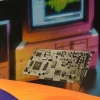
For now I've installed just some wire between the two points and use the speaker's volume control instead, which is very noisy, but it works as a proof of function. The pictures show a potentiometer, but it doesn't do anything, the jumper wires perform the same function.
The card bracket is 3d printed and once I've tried it out in a proper case, I'll add the files for that for anyone else that wants to print one out.
The CMS audio is working and sounds quite nice. PCM audio is working too (I'd forgotten just how mono the original sound blaster is), but FM sound just gives a distorted quiet mess - I wonder if it's the Y3014B DAC (which is maybe fake & maybe damaged), or if I mixed up a capacitor value?
I should get the replacement Y3014B DAC tomorrow to test 😀
My money is on the dac, if it's bad opl will sound exactly like that
Great 😀 I was initially thinking it could be the op-amp/mixer but the CMS and normal audio works okay so it's less likely to be that.
I assume these older chips like the YM3812 and YM3014 are quite sensitive to static / mishandling?
Isn't this card technically an SB 1.5 clone; I believe we had established that the image used for the flash chip is the DSP from 1.5? or am I off completely? Just started building mine, so a bit curious..
wrote:Isn't this card technically an SB 1.5 clone; I believe we had established that the image used for the flash chip is the DSP from 1.5? or am I off completely? Just started building mine, so a bit curious..
Is there a difference in DSP between 1.0 and 1.5?
I thought the main difference was that the 1.5 no longer came with the CMS chips installed from the factory.
wrote:wrote:Isn't this card technically an SB 1.5 clone; I believe we had established that the image used for the flash chip is the DSP from 1.5? or am I off completely? Just started building mine, so a bit curious..
Is there a difference in DSP between 1.0 and 1.5?
I thought the main difference was that the 1.5 no longer came with the CMS chips installed from the factory.
DSP versions can differ, depending on age of the card:
http://www.amoretro.de/guides-workshops/creat … r-modellnummern
wrote:DSP versions can differ, depending on age of the card:
http://www.amoretro.de/guides-workshops/creat … r-modellnummern
Right, so you can have 1.03, 1.05 or 2.00.
2.00 is the auto-init update. I hope that's the one the Snark Barker uses.
@root42
did you ever test the real 2.01 dsp with the snark barker?
wrote:wrote:DSP versions can differ, depending on age of the card:
http://www.amoretro.de/guides-workshops/creat … r-modellnummern
Right, so you can have 1.03, 1.05 or 2.00.
2.00 is the auto-init update. I hope that's the one the Snark Barker uses.
The SnarkBarker uses a DSP firmware from some SB clone. Haven't checked the version yet. Keropi also was kind enough to provide me with an original SB DSP on a PLCC to DIP adapter. However it doesn't fit in my socket on the Snark Barker. I'll have to desolder the socket, then I can test that.
wrote:@root42
did you ever test the real 2.01 dsp with the snark barker?
See above! It's on my todo list. Since I now have TWO SnarkBarkers I can try to desolder the socket of one of them...
If it works on the SnarkBarker, I wonder what the difference is on the real SB 1.x vs 2.0.
The 2.01 DSP introduces higher sampling rates. But is the SB 1.x physically incapable of that, or is it just because the DSP chip used a different form-factor, and they did not want some nasty retro-fit solution on the existing SB 1.x socket?
The auto-init and better MIDI functionality were in the 2.00 DSP, so that part worked on the old PCB at least.
root42
is it a dual-whipe socket? you whould be able to force that in ...
- there are some options to consider: replace the pins on the adapter with slimmer or round ones
- insert on the adapter some female->male pins and insert those to the socket (so any damage is made on the intermediate pins and not the socket)
you an also try to remove the socket pin-by-pin , destroying it in the process but it's safer for the pcb
A firmware on Snark Barker's github is actually a 2.01 DSP firmware.
Its E1 command code look like this:
; ------------------------------------------------------------------------------
; E1 - Get a version of DSP, major byte first, minor byte next
CMD_E1_Get_DSP_Version:
CLR DSP_BUSY
JNB DMA_EN, L0A4C ; Jump away if /DMA_EN is low (DMA enabled)
MOV A, #002H ; Write major version byte
L09F5:
JB DAV_PC, L09F5
MOVX @R0, A
MOV A, #001H ; Write minor version byte
L09FB:
JB DAV_PC, L09FB
MOVX @R0, A
LJMP DSP_Idle
; NOT REACHED
And it has 0x90 and 0x91 (high speed playback) functions code.
So it should run as SB2.0
Interesting.
@root42 did you ever do an SBCHECK on the clone DSP firmware for the Snark Barker? Do you know what it reports?