VOGONS


First post, by kalm_traveler

User metadata
Rank Member
Rank
Member

Short version of the story is I recapped an Enermax Noisetaker PSU and am transplanting it into a modern EVGA shell to make it modular but I was stupid and didn't take adequate pictures of where all the wires went before removing it's original harness.

Now, between the one picture I have, the single picture I was able to find on Google Images from ~ 2006, and the board itself generally being labeled I have figured out where all the wires go except for 2: the GND sense and +3.3v sense wires. (the EVGA unit also had +12v and +5v sense wires on its modular PCB that I'm reusing but there were no such wires in the Enermax harness).

So my question now is how necessary should these be to use the PSU? I've looked at the 2 pictures I have on hand and can't for the life of me figure out where they were originally soldered to on the Enermax PSU PCB.

Last resort is going to be buying another almost-identical unit off ebay for ~ $40 shipped to tear down and compare as I'm sure they use the same PCB based on the markings on mine but I'd rather not spend that just to see where 2 wires go if possible, especially since I've already got an itch to build the Windows Xp rig my in sig.

What do you guys think?

Retro: Win2k/98SE - P3 1.13ghz, 512mb PC133 SDRAM, Quadro4 980XGL, Aureal Vortex 2
modern:i9 10980XE, 64gb DDR4, 2x Titan RTX | i9 9900KS, 32gb DDR4, RTX 2080 Ti | '19 Razer Blade Pro
Reply 1 of 26, by Tiido

User metadata
Rank l33t
Rank
l33t

If those signals do not connect to the relevant places I expect the voltage regulation to be all over the place, probably well over nominals and possibly tripping overvoltage protection if present.

T-04YBSC, a new YMF71x based sound card & Official VOGONS thread about it
Newly made 4MB 60ns 30pin SIMMs ~
mida sa loed ? nagunii aru ei saa 😜

Reply 2 of 26, by Horun

User metadata
Rank l33t++
Rank
l33t++

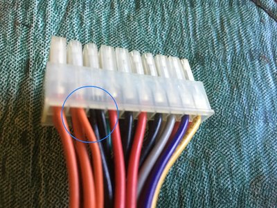
Just checked one of my ATX with 20 pin, it has the 3.3 sense connected with a main +3.3v supply wire at pin 2, the GND sense is connected with main GND at pin 3. Here is a pic and you can sorta make out how there are two wires going to each of those two pins.

Attachments

  • 3v sense.jpg
    Filename
    3v sense.jpg
    File size
    1.25 MiB
    Views
    953 views
    File license
    Fair use/fair dealing exception

Hate posting a reply and then have to edit it because it made no sense 😁 First computer was an IBM 3270 workstation with CGA monitor. Stuff: https://archive.org/details/@horun

Reply 3 of 26, by kalm_traveler

User metadata
Rank Member
Rank
Member
Horun wrote:

Just checked one of my ATX with 20 pin, it has the 3.3 sense connected with a main +3.3v supply wire at pin 2, the GND sense is connected with main GND at pin 3. Here is a pic and you can sorta make out how there are two wires going to each of those two pins.

thank you - the problem I have is that I don't know where the wires go on the PSU's circuit board though.

May just need to buy another one to tear apart like I mentioned in the first post 🙁

Retro: Win2k/98SE - P3 1.13ghz, 512mb PC133 SDRAM, Quadro4 980XGL, Aureal Vortex 2
modern:i9 10980XE, 64gb DDR4, 2x Titan RTX | i9 9900KS, 32gb DDR4, RTX 2080 Ti | '19 Razer Blade Pro
Reply 4 of 26, by Horun

User metadata
Rank l33t++
Rank
l33t++

Ahh ok I misunderstood, inside my psu case the 3v sense goes to solder thru hole with s+ (micro stamped on top of pcb) and the gnd sense does same to a s- right next to. Any marking on the PSU board you have ?

Hate posting a reply and then have to edit it because it made no sense 😁 First computer was an IBM 3270 workstation with CGA monitor. Stuff: https://archive.org/details/@horun

Reply 5 of 26, by gdjacobs

User metadata
Rank l33t++
Rank
l33t++
Tiido wrote:

If those signals do not connect to the relevant places I expect the voltage regulation to be all over the place, probably well over nominals and possibly tripping overvoltage protection if present.

Yup, they'll be required for voltage regulation. It's best to sense as close to the load as possible (at the connector) so the PSU can compensate for cable losses.

All hail the Great Capacitor Brand Finder

Reply 6 of 26, by kalm_traveler

User metadata
Rank Member
Rank
Member
Horun wrote:

Ahh ok I misunderstood, inside my psu case the 3v sense goes to solder thru hole with s+ (micro stamped on top of pcb) and the gnd sense does same to a s- right next to. Any marking on the PSU board you have ?

AH you may have just saved my bacon in that case.

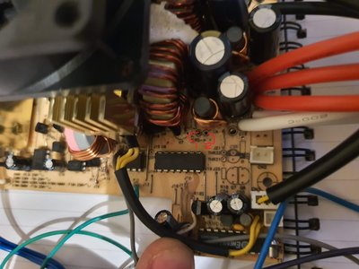
This is the area where I saw the wires disappear in the only photo I took before desoldering everything, and the spots I marked as 1 and 2 read RS- and RS+ respectively.

Reasonably certain that has to be where they go now as there are no other marked spots that seem even remotely similar anywhere on the board, let alone in the region where I can tell they routed originally.

Thank you! Standby - need to discharge the capacitors real quick and get those last 2 wires soldered up!

*EDIT*

hmm well that didn't do the trick at least. 5v standby is there, and if I bridge the 2 ATX pins to turn the PSU on its fans (and a connected fan on a 4 pin molex) bump for just a moment but then stop.

Not really sure what would be wrong at this point. I might just buy another PSU and start over. Everything just barely fits in the EVGA housing, but its all for naught if it won't even work anymore.

Attachments

  • 20191026_183611.jpg
    Filename
    20191026_183611.jpg
    File size
    269.47 KiB
    Views
    908 views
    File license
    Fair use/fair dealing exception

Retro: Win2k/98SE - P3 1.13ghz, 512mb PC133 SDRAM, Quadro4 980XGL, Aureal Vortex 2
modern:i9 10980XE, 64gb DDR4, 2x Titan RTX | i9 9900KS, 32gb DDR4, RTX 2080 Ti | '19 Razer Blade Pro

Reply 7 of 26, by kalm_traveler

User metadata
Rank Member
Rank
Member

in case anybody was following - I decided to pick up another Enermax PSU from this same product line, though only the 425w version (I am using the 600w version for ULTIMATE POWAH) and a larger donor shell so that I don't have to smash the extra wiring in there so a Corsair HX750i should be perfect.

For you electrical engineer types, it occurred to me that I combined both +12v rails into the same modular plate input - might that be the cause of the PSU bumping on for just a moment and then not actually coming on all the way?

Retro: Win2k/98SE - P3 1.13ghz, 512mb PC133 SDRAM, Quadro4 980XGL, Aureal Vortex 2
modern:i9 10980XE, 64gb DDR4, 2x Titan RTX | i9 9900KS, 32gb DDR4, RTX 2080 Ti | '19 Razer Blade Pro

Reply 8 of 26, by gdjacobs

User metadata
Rank l33t++
Rank
l33t++
kalm_traveler wrote:

in case anybody was following - I decided to pick up another Enermax PSU from this same product line, though only the 425w version (I am using the 600w version for ULTIMATE POWAH) and a larger donor shell so that I don't have to smash the extra wiring in there so a Corsair HX750i should be perfect.

For you electrical engineer types, it occurred to me that I combined both +12v rails into the same modular plate input - might that be the cause of the PSU bumping on for just a moment and then not actually coming on all the way?

Could be. For instance, if the rail voltages are slightly out of balance, combining them can result in a quasi short circuit.

All hail the Great Capacitor Brand Finder

Reply 9 of 26, by Horun

User metadata
Rank l33t++
Rank
l33t++
kalm_traveler wrote:

For you electrical engineer types, it occurred to me that I combined both +12v rails into the same modular plate input - might that be the cause of the PSU bumping on for just a moment and then not actually coming on all the way?

You never mentioned that before and yeah that would be a def NO-NO ! 🤣 They split the rails to differant connectors on purpose on multi rail PSU. 12v1 typically goes just to motherboard/cpu and 12v2 goes to PCIe and molex (ide, sata, etc) or some variation of that but the you never see both going to the motherboard AFAIK

Hate posting a reply and then have to edit it because it made no sense 😁 First computer was an IBM 3270 workstation with CGA monitor. Stuff: https://archive.org/details/@horun

Reply 10 of 26, by kalm_traveler

User metadata
Rank Member
Rank
Member
Horun wrote:
kalm_traveler wrote:

For you electrical engineer types, it occurred to me that I combined both +12v rails into the same modular plate input - might that be the cause of the PSU bumping on for just a moment and then not actually coming on all the way?

You never mentioned that before and yeah that would be a def NO-NO ! 🤣 They split the rails to differant connectors on purpose on multi rail PSU. 12v1 typically goes just to motherboard/cpu and 12v2 goes to PCIe and molex (ide, sata, etc) or some variation of that but the you never see both going to the motherboard AFAIK

ah good to know, thank you! I won't have time to tinker with this until next weekend but I'll split them up and see if that gets it to work. Also will have the spare Enermax unit for comparison as well as the larger Corsair HX750i shell for final assembly etc. I believe it also has 2 12v rails so maybe I'll be able to connect them separately as the Enermax PSU guts need.

Retro: Win2k/98SE - P3 1.13ghz, 512mb PC133 SDRAM, Quadro4 980XGL, Aureal Vortex 2
modern:i9 10980XE, 64gb DDR4, 2x Titan RTX | i9 9900KS, 32gb DDR4, RTX 2080 Ti | '19 Razer Blade Pro

Reply 11 of 26, by kalm_traveler

User metadata
Rank Member
Rank
Member

hmm now I'm confused... the 470w Enermax CPU arrived so I could pop it open and make sure that I had all the wires in the correct locations on the existing 600w unit.

Everything is in the correct spot, I didn't reverse any of the new caps, and just to double check the 'new' PSU powers on fully with the 2 mb connector pins bridged.

Now I'm a bit stumped as to why the original 600w unit won't fully turn on. I split up the 12v rails as well in case that had been the problem.

On the flip side, since the 470w unit seems to work just fine I may end up swapping the new caps over to it and just using that one instead since it has almost exactly the same +3.3v and +5v output as the 600w unit which is what I wanted an old PSU for in the first place.

Retro: Win2k/98SE - P3 1.13ghz, 512mb PC133 SDRAM, Quadro4 980XGL, Aureal Vortex 2
modern:i9 10980XE, 64gb DDR4, 2x Titan RTX | i9 9900KS, 32gb DDR4, RTX 2080 Ti | '19 Razer Blade Pro

Reply 12 of 26, by gdjacobs

User metadata
Rank l33t++
Rank
l33t++

What series, voltage, and dimensions were the caps you replaced? What series, voltage, and dimensions did you replace them with? Depending on the feedback design of the PSU, straying too far from the original capacitor's ESR can result in loss of regulation which causes the PWR_OK signal to not go active (in proper PSUs that don't simply strap it active).

All hail the Great Capacitor Brand Finder

Reply 13 of 26, by kalm_traveler

User metadata
Rank Member
Rank
Member
gdjacobs wrote:

What series, voltage, and dimensions were the caps you replaced? What series, voltage, and dimensions did you replace them with? Depending on the feedback design of the PSU, straying too far from the original capacitor's ESR can result in loss of regulation which causes the PWR_OK signal to not go active (in proper PSUs that don't simply strap it active).

Pardon my ignorance but I'm not familiar with a capacitor series... What I did was go to digikey and order identical dimension electrolytic caps with the same voltage and microfarad measurements as what came off the board originally.

I still have the originals if you'd like to see a picture of them all.

Retro: Win2k/98SE - P3 1.13ghz, 512mb PC133 SDRAM, Quadro4 980XGL, Aureal Vortex 2
modern:i9 10980XE, 64gb DDR4, 2x Titan RTX | i9 9900KS, 32gb DDR4, RTX 2080 Ti | '19 Razer Blade Pro

Reply 14 of 26, by gdjacobs

User metadata
Rank l33t++
Rank
l33t++

Just to be clear, I'm not sure if my theory is the cause of what's happening, but it is possible and is known to have happened in the past.

Caps will often have a manufacturers mark or full name on the casing, although this is sometimes omitted by the more shady operators. They will also have a two or three letter code group which corresponds loosely with a set of common set of performance parameters which makes a particular series useful for similar applications. Matching the manufacturer, series, voltage, and case dimensions allows you to find full performance specs in the datasheets.

If you can send me pictures from all sides, I can help you track down the info you'll need to see how well the replacements match.

All hail the Great Capacitor Brand Finder

Reply 15 of 26, by Matth79

User metadata
Rank Oldbie
Rank
Oldbie

For switchmode power supplies, they would also have to be low esr, though in some cases, going far lower in esr than originally designed for may also upset the circuit - I believe someone tried converting a PSU to polymers, but a big part of the problem with that may have been having to make do with considerably lower capacitance for some.

Reply 16 of 26, by kalm_traveler

User metadata
Rank Member
Rank
Member
gdjacobs wrote:

Just to be clear, I'm not sure if my theory is the cause of what's happening, but it is possible and is known to have happened in the past.

Caps will often have a manufacturers mark or full name on the casing, although this is sometimes omitted by the more shady operators. They will also have a two or three letter code group which corresponds loosely with a set of common set of performance parameters which makes a particular series useful for similar applications. Matching the manufacturer, series, voltage, and case dimensions allows you to find full performance specs in the datasheets.

If you can send me pictures from all sides, I can help you track down the info you'll need to see how well the replacements match.

I can take a picture if need be but here are the markings on all of them:

two of:
CE(M)
UQ 85 C (this says 85 degrees C)
1200 uf
200v
3221A

two of:
(side 1)
4700 uf
10V
VENT
(side 2)
PCE-TUL
105 C (this says 105 degrees C)
0401

two of:
(side 1)
3300 uF
10 V
VENT
(side 2)
PCE-TUR
105 C (this says 105 degrees C)
0401

one of:
(side 1)
2200 uF
16 V
VENT
(side 2)
PCE-TUR
105 C (this says 105 degrees C)
0401

two of:
(side 1)
1000 uF
10 V
VENT
(side 2)
PCE-TUR
105 C (this says 105 degrees C)
0401

one of:
(side 1)
470 uF
25 V
VENT
(side 2)
PCE-TUR
105 C (this says 105 degrees C)
0401
-----------

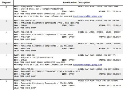
And attached are the part numbers I ordered from DigiKey

Attachments

  • digikeyorder.jpg
    Filename
    digikeyorder.jpg
    File size
    110.14 KiB
    Views
    653 views
    File license
    Fair use/fair dealing exception

Retro: Win2k/98SE - P3 1.13ghz, 512mb PC133 SDRAM, Quadro4 980XGL, Aureal Vortex 2
modern:i9 10980XE, 64gb DDR4, 2x Titan RTX | i9 9900KS, 32gb DDR4, RTX 2080 Ti | '19 Razer Blade Pro

Reply 17 of 26, by gdjacobs

User metadata
Rank l33t++
Rank
l33t++
kalm_traveler wrote:
two of: CE(M) UQ 85 C (this says 85 degrees C) 1200 uf 200v 3221A […]
Show full quote

two of:
CE(M)
UQ 85 C (this says 85 degrees C)
1200 uf
200v
3221A


Panasonic UQ series. All three sizes for this series, capacitance, and voltage combination are 0.075ohms ESR @ 20 khz. ESR usually isn't sensitive for bulk caps like this.

kalm_traveler wrote:
two of: (side 1) 4700 uf 10V VENT (side 2) PCE-TUL 105 C (this says 105 degrees C) 0401 […]
Show full quote

two of:
(side 1)
4700 uf
10V
VENT
(side 2)
PCE-TUL
105 C (this says 105 degrees C)
0401


CEC TUL series, 0.023 ohms at 100khz, 2.5A RMS ripple. Panny HD is not a good match for these. FC or FK in the same case size, voltage, and capacitance would be better.

kalm_traveler wrote:
two of: (side 1) 3300 uF 10 V VENT (side 2) PCE-TUR 105 C (this says 105 degrees C) 0401 […]
Show full quote

two of:
(side 1)
3300 uF
10 V
VENT
(side 2)
PCE-TUR
105 C (this says 105 degrees C)
0401


CEC TUR series, ripple current ~ 1.5A RMS.

kalm_traveler wrote:
one of: (side 1) 2200 uF 16 V VENT (side 2) PCE-TUR 105 C (this says 105 degrees C) 0401 […]
Show full quote

one of:
(side 1)
2200 uF
16 V
VENT
(side 2)
PCE-TUR
105 C (this says 105 degrees C)
0401


TUR series, ripple current ~ 1.2A RMS

kalm_traveler wrote:
two of: (side 1) 1000 uF 10 V VENT (side 2) PCE-TUR 105 C (this says 105 degrees C) 0401 […]
Show full quote

two of:
(side 1)
1000 uF
10 V
VENT
(side 2)
PCE-TUR
105 C (this says 105 degrees C)
0401


TUR series, ripple current ~0.7A RMS

kalm_traveler wrote:
one of: (side 1) 470 uF 25 V VENT (side 2) PCE-TUR 105 C (this says 105 degrees C) 0401 ----------- […]
Show full quote

one of:
(side 1)
470 uF
25 V
VENT
(side 2)
PCE-TUR
105 C (this says 105 degrees C)
0401
-----------


TUR series, ripple current ~ 0.6A RMS

The TUR series caps are general purpose. The Panny and Ruby caps specified to replace these are perhaps a bit over spec (being low or low-ish ESR), but the Panny HD is much more of a mismatch and therefore what I would substitute first.

All hail the Great Capacitor Brand Finder

Reply 18 of 26, by kalm_traveler

User metadata
Rank Member
Rank
Member
gdjacobs wrote:

The TUR series caps are general purpose. The Panny and Ruby caps specified to replace these are perhaps a bit over spec (being low or low-ish ESR), but the Panny HD is much more of a mismatch and therefore what I would substitute first.

thank you - I'm not sure how to identify which Panasonic are HD or not, so should I just replace all of them? and which type should I be looking for on DigiKey for replacements?

Retro: Win2k/98SE - P3 1.13ghz, 512mb PC133 SDRAM, Quadro4 980XGL, Aureal Vortex 2
modern:i9 10980XE, 64gb DDR4, 2x Titan RTX | i9 9900KS, 32gb DDR4, RTX 2080 Ti | '19 Razer Blade Pro

Reply 19 of 26, by gdjacobs

User metadata
Rank l33t++
Rank
l33t++

The HD caps are the 4700uF ones. Again, Panny FC, FK, or FM caps, 10V, 4700uF would be excellent.

All hail the Great Capacitor Brand Finder