VOGONS


First post, by xjas

User metadata
Rank l33t
Rank
l33t

So following imi's recent scores, I decided I needed four G200s on a single card in my life too. 😜

The attachment 20191122_125637.jpg is no longer available

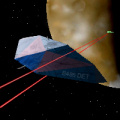
Unfortunately the card I picked up is pretty beaten up & has some damage, two tiny SMD capacitors have sheared off the board. C319 and C213, as indicated here:

The attachment quad_damage.jpg is no longer available
The attachment 20191122_131427.jpg is no longer available
The attachment 20191122_131454.jpg is no longer available

The annoying part is they took the solder pads with them. C319 is still hanging there by a thread (only on one side), but C213 is long gone. I don't know its value but every other SMD cap of this type on the board is an A106 so I'm guessing it's the same.

I fired it up anyway, and it does work - more or less. The card was detected and the drivers & software installed fine, and it shows up in the control panel as it should. Outputs 1, 3, and 4 work fine, but #2 gives me a completely black screen. It actually reads the EDID on that port and the monitor seems to sync up & change video modes appropriately, there's just no picture.

I had a good look over the rest of the card, but those are the only two broken components I can see. Quite a few empty solder pads but it doesn't look like they were ever populated.

Not sure if this is related, but I get some vertical lines on the screen (in the sky) and some textures/sprites don't display properly. For all I know the texturing is just standard G200 behavior, and it doesn't happen in every game. The vertical banding only happens in OGL/D3D stuff and not on the desktop.

The attachment 20191122_141034.jpg is no longer available

So yeah, looking for advice on how to repair this. I don't need it to look pretty, just work. If the solder pads hadn't been torn off it'd be an easy fix, but I can't even test for continuity because there's nothing left where they were. This is a horrendously complicated card and it's not obvious to me where I could run a jump wire to.

Anyone have a schematic?

twitch.tv/oldskooljay - playing the obscure, forgotten & weird - most Tuesdays & Thursdays @ 6:30 PM PDT. Bonus streams elsewhen!

Reply 1 of 6, by derSammler

User metadata
Rank l33t
Rank
l33t

As for C213, the missing pad was connected to the via directly below (or above, if the card is not upside down). It's very clear to see in the picture.

Reply 2 of 6, by Errius

User metadata
Rank l33t
Rank
l33t

Are you planning to play games on this card? Because it's very weak.

I have the version with support for two monitors and no TV tuner. I don't think it's damaged but it also produced screen corruption running 3DMark2000 in Windows XP. I don't think the drivers for these cards are good with games.

Is this too much voodoo?

Reply 3 of 6, by xjas

User metadata
Rank l33t
Rank
l33t
Errius wrote:

Are you planning to play games on this card? Because it's very weak.

I have the version with support for two monitors and no TV tuner. I don't think it's damaged but it also produced screen corruption running 3DMark2000 in Windows XP. I don't think the drivers for these cards are good with games.

I am aware it's not the best gaming card in the world... I bought it to mess around with making a Win98-powered video wall, which is absolutely a productive use my my time & money in 2019, and it's literally what these cards were made for. I have lots of better gaming cards but none with quad-head support.

derSammler wrote:

As for C213, the missing pad was connected to the via directly below (or above, if the card is not upside down). It's very clear to see in the picture.

Do you mean here? If so, that's not too bad... There are little contact points like that for the other cap too. They're TINY, but doable.

The attachment 20191122_131454_2.jpg is no longer available

^^ this pic is about 4x actual size on a 13" laptop screen BTW.

Can I replace these SMD caps with a through-hole tantalum of the same rating, or are they "special" somehow? I think it'd be easier if I had legs to solder to.

twitch.tv/oldskooljay - playing the obscure, forgotten & weird - most Tuesdays & Thursdays @ 6:30 PM PDT. Bonus streams elsewhen!

Reply 4 of 6, by derSammler

User metadata
Rank l33t
Rank
l33t

Yes, that's the spot I mean. Also yes, you can replace that cap with a tantalum one.

Reply 5 of 6, by xjas

User metadata
Rank l33t
Rank
l33t

Update: well, I managed to replace the missing caps - sort of. For C319 (at the front of the card) I replaced the original one, but on C213 (under GPU #2), I used an appropriately-rated electrolytic since my local shop didn't have any tantalums.

The attachment 20200112_181724.jpg is no longer available
The attachment 20200112_181700.jpg is no longer available
The attachment 20200112_181633.jpg is no longer available

Incidentally working on these was pretty hard, this stuff is TINY. I was able to determine with a multimeter that my solder joints are "good" and both sides of each cap connect to where I think they're supposed to, but I didn't try to test their capacitance in-situ (my meter can't do that.)

Results:
- the texture corruption (see Drakan screenshot, above) in 3D games is fixed. To be honest, that wasn't the problem I was expecting to fix, but I'll take it.
- the vertical banding is still present in 3D games (not on the desktop as far as I can tell)
- GPU #2 still just shows a black screen 🙁

The weird thing with GPU #2 is the sync signals are apparently present, the monitor on that display shows the right resolution & refresh, and responds when you change it independently of the others. Just the picture shows up black.

My "hypothesis" is that C213 is part of an amplifier circuit for the RGB signals (only!) on that GPU? Maybe the electrolytic I used can't charge and discharge fast enough to cope with a video signal??

I would love to hear some other opinions on this!

The technical reference for the G200 is available, but I'm not an engineer, and without a schematic for this specific card, I haven't been able to figure out what those components actually do...

I did harvest some 10µF tantalums from another board (through hole - the yellow blob type), but 20+ year old recycled tantalums tend to go 'pop', so I didn't wanna use them. Soldering & de-soldering on this spot was a big enough pain I don't want to do it unnecessarily. Is it worth trying one?

twitch.tv/oldskooljay - playing the obscure, forgotten & weird - most Tuesdays & Thursdays @ 6:30 PM PDT. Bonus streams elsewhen!

Reply 6 of 6, by Tiido

User metadata
Rank l33t
Rank
l33t

Capacitor type isn't gonna have such an effect, or shouldn't anyway. There ripped pad might connect to more than one place and things won't work if all those got connected. The card has 4x copies so you could desolder parts on the other sections to see exactly where things end up and restore things on the faulty part.
There's also a missing part on the repair near connector end, a small capacitor it looks like.

T-04YBSC, a new YMF71x based sound card & Official VOGONS thread about it
Newly made 4MB 60ns 30pin SIMMs ~
mida sa loed ? nagunii aru ei saa 😜