VOGONS


First post, by NyLan

User metadata
Rank Member
Rank
Member

Hi guys

I just got a Geforce 2 GTS but I would like your input before I try to plug it.

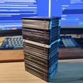
On the first picture you can see a jumper on the top left corner, near the GPU Heatsink. The current position is maybe the right one, maybe not.
I do not understand how it supposed to be set. Having a closer view it seems someone put it wrongly and burned 1 or 2 jumpers on it.

closer IMG_9048.JPG
Filename
closer IMG_9048.JPG
File size
65.46 KiB
Views
448 views
File license
Fair use/fair dealing exception

the card :

IMG_9048.JPG
Filename
IMG_9048.JPG
File size
1.57 MiB
Views
448 views
File license
Fair use/fair dealing exception

closer view

IMG_20200824_191305.jpg
Filename
IMG_20200824_191305.jpg
File size
125.14 KiB
Views
448 views
File license
Fair use/fair dealing exception

I'm wondering if I can start it without any of the jumper, or if I should not try at all. Don't want to burn my mobo 🙁

My Intel SE440BX-2 Intel's website Mirror : Modified to include docs, refs and BIOSes.
Proud owner of a TL866 II
Personal GitHub

Reply 2 of 9, by NyLan

User metadata
Rank Member
Rank
Member

agree on that point 😀
But I do not understand if this position is right or not

My Intel SE440BX-2 Intel's website Mirror : Modified to include docs, refs and BIOSes.
Proud owner of a TL866 II
Personal GitHub

Reply 3 of 9, by Doornkaat

User metadata
Rank l33t
Rank
l33t

There are two jumpers with two positions each.
Upper row is JP1, lower row JP2. You use a jumper to connect the middle pin to one of the outer pins one each row.
Right now you have position 2 on JP1 shorted with position 2 on JP2. This is not a valid setting as far as the silkscreen goes.

Reply 5 of 9, by NyLan

User metadata
Rank Member
Rank
Member

I see, it make sense !
I believe they tried wrong position and that caused short circuit and burned the jumper.
I'm now wondering if it's safe to test this graphic card on my mobo 🤔

My Intel SE440BX-2 Intel's website Mirror : Modified to include docs, refs and BIOSes.
Proud owner of a TL866 II
Personal GitHub

Reply 6 of 9, by debs3759

User metadata
Rank Oldbie
Rank
Oldbie

If it's just the plastic ob the pins that is damaged (ie if nearby traces and components are undamaged) it should be OK. I would test it if I had it.

See my graphics card database at www.gpuzoo.com
Constantly being worked on. Feel free to message me with any corrections or details of cards you would like me to research and add.

Reply 7 of 9, by Horun

User metadata
Rank l33t++
Rank
l33t++
Warlord wrote on 2020-08-24, 22:10:
No thats not right. 123 OOO<-----JP1 123 OOO<-----jp2 […]
Show full quote

No thats not right.
123
OOO<-----JP1
123
OOO<-----jp2

NTSC
1-2
XXO
PAL
2-3
OXX

NTSC means USA, Japan
PAL means Europe

debs3759 wrote on 2020-08-24, 23:29:

If it's just the plastic ob the pins that is damaged (ie if nearby traces and components are undamaged) it should be OK. I would test it if I had it.

Agree ! Worth testing and having them in wrong postions should not have shorted anything out.

Hate posting a reply and then have to edit it because it made no sense 😁 First computer was an IBM 3270 workstation with CGA monitor. https://archive.org/details/@horun

Reply 8 of 9, by shamino

User metadata
Rank l33t
Rank
l33t

I'm guessing the center pin on each row goes to a different signal connection, probably on that CH7007A chip.
The outer pins on each row are probably +5V and GND, or similar. Setting the jumpers would signal each of those lines with one of those voltage levels.

Somehow it seems the outer pins are the ones that got burned - like somebody tied the outer pins together. I'm not sure how that would happen without deliberate effort.

The fact that the plastic burned means something got hot and a lot of current was flowing. Damage seems likely.
If anything is damaged then hopefully it's just the TV out feature.

To be safe, I'd find an AGP pinout and check for shorts between any of the voltage lines to GND with a multimeter.
If you have a junk motherboard smoke test it in that first.
Otherwise, at least use a good PSU that you trust with overcurrent protection, and which preferably does *not* have gobs of amperage capacity (you want it to trip before your motherboard does).

Reply 9 of 9, by NyLan

User metadata
Rank Member
Rank
Member
shamino wrote on 2020-08-26, 14:45:

I'm guessing the center pin on each row goes to a different signal connection, probably on that CH7007A chip.
The outer pins on each row are probably +5V and GND, or similar. Setting the jumpers would signal each of those lines with one of those voltage levels.

That was a good guess and advice
So I took my multimeter and figured out the below

jumpers.jpg
Filename
jumpers.jpg
File size
126.98 KiB
Views
322 views
File license
Fair use/fair dealing exception

So the previous owner put the jumper directly on GND - 3.3V twice...
By the way, I really feel this is a design issue from the manufacturer to put GND pins that near to 3.3V pins without any reason since it's not used in any "official" position

Now I'm just wondering if I take the risk to put this card on a current motherboard I have, or If I can use this excuse to buy another one 😀

My Intel SE440BX-2 Intel's website Mirror : Modified to include docs, refs and BIOSes.
Proud owner of a TL866 II
Personal GitHub