First post, by dataino.it

- Rank
- Member
I bet with a seller on ebay that I would fix his battery acid-ravaged motherboard. The premium an 80% discount on two other motherboards.
The steps I recommend from my experience to win are these:
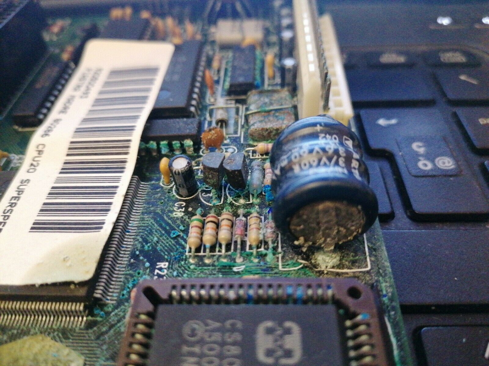
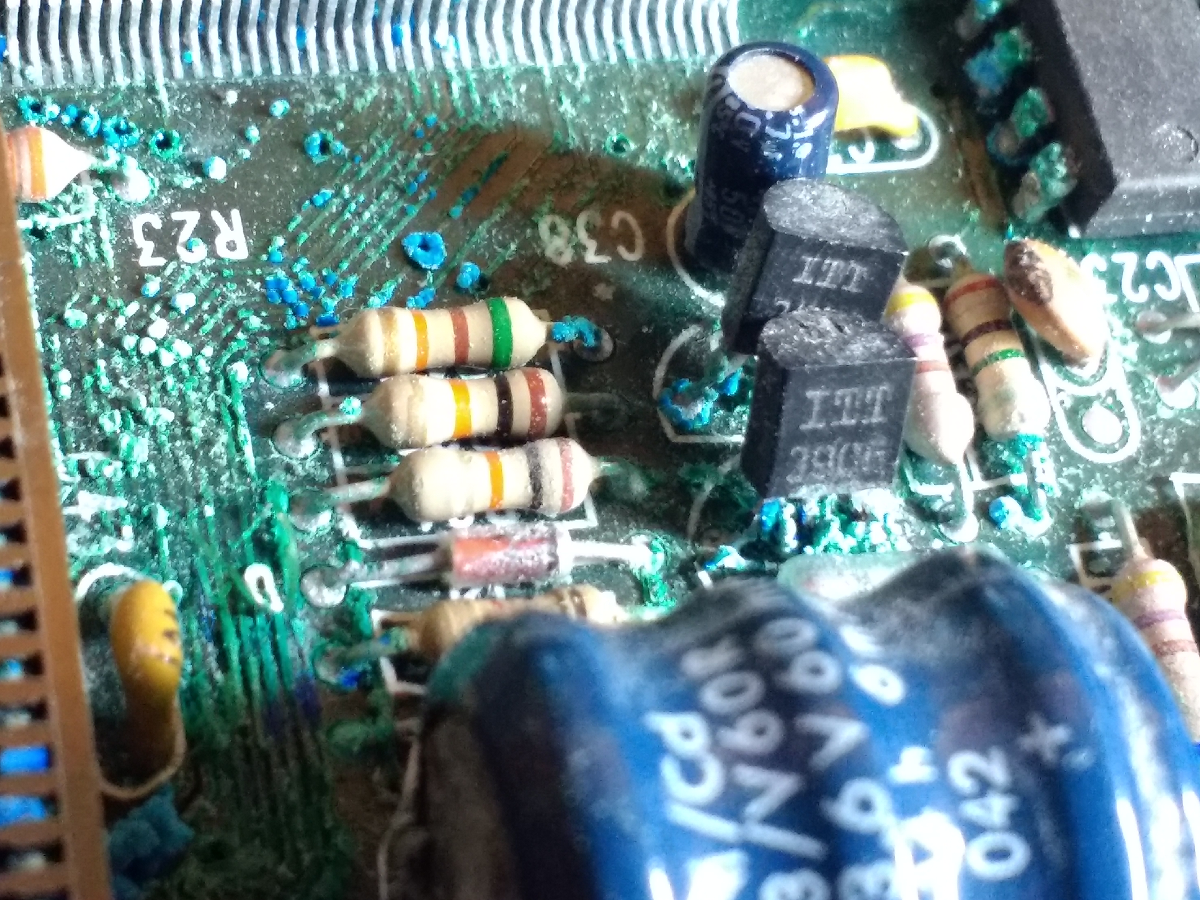
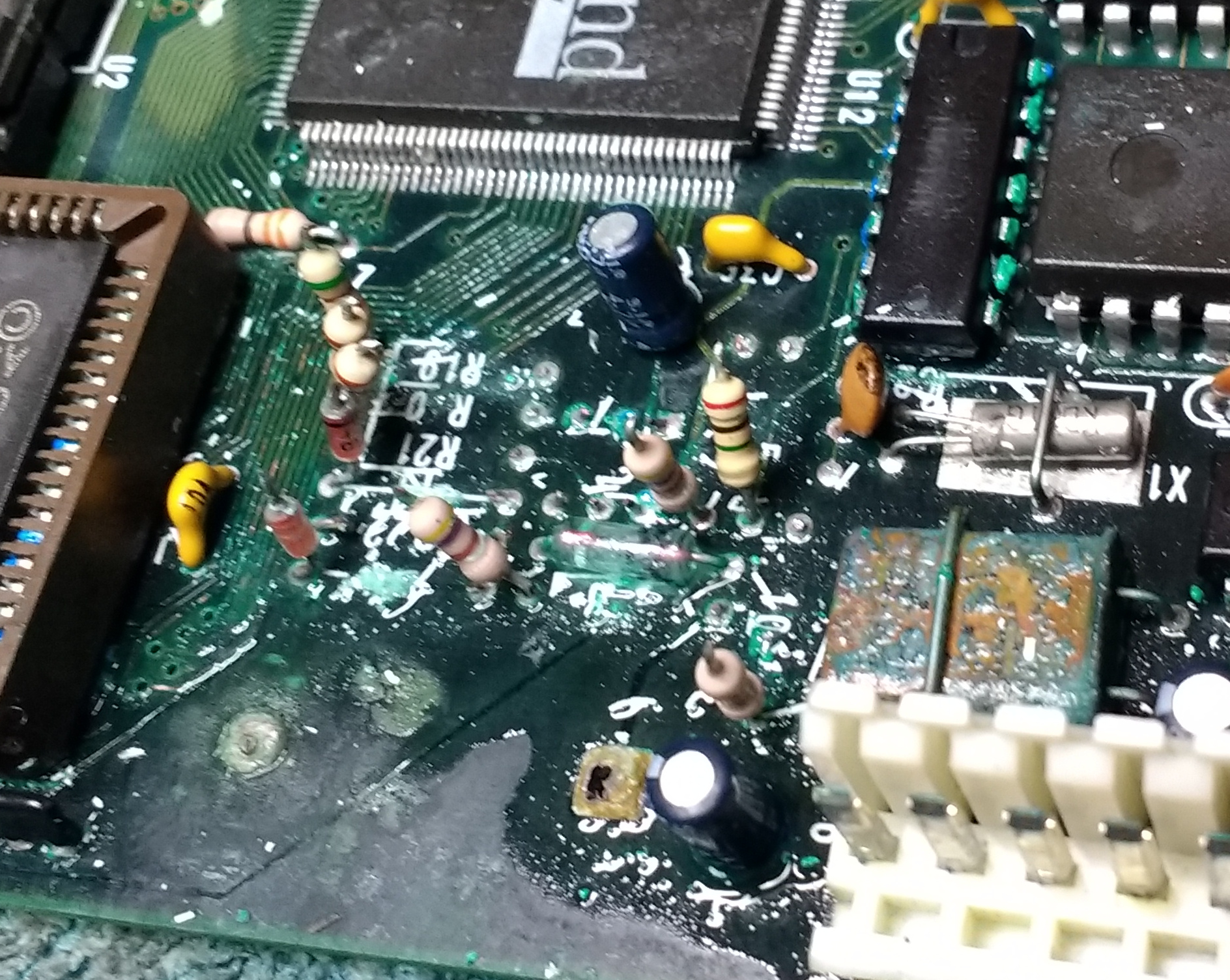
1 ) Photographing every detail.
[+] Before any intervention, take a good picture of all the components involved
Folding them if necessary to read their values
Take photos from different angles
Take pictures of the entire motherboard
Here's what happens to a component when it is cleaned with vinegar or other products
The writing becomes illegible this applies to the integrated but especially to the ceramic capacitors, diodes and other components
2 ) Removal of components
[+] Eliminate as many components as possible
It is necessary to shed some light on the circuit board to be able to highlight all the damaged tracks.
Affected solder points should be scratched and stagnated before attempting
the suction of the pond.
Always use flux paste in the two phases.
Remove components in this way where the situation is simple but it does
procedure described above does not work, in the case of components
easy to find, proceed with the cutting of the feet leaving them as much
long as possible. The resistors and diodes only on one side, for the integrated cutting them all
Then they are eliminated with the help of tweezers and soldering iron.
At this point we proceed with the emptying of the pitches from the pond.
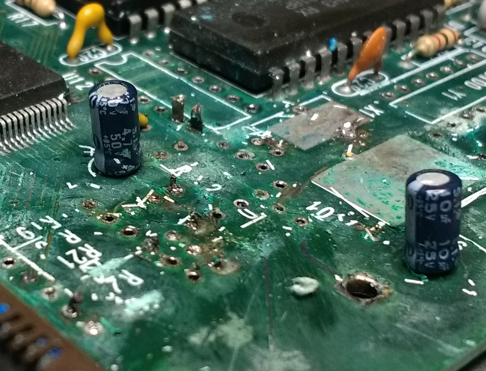
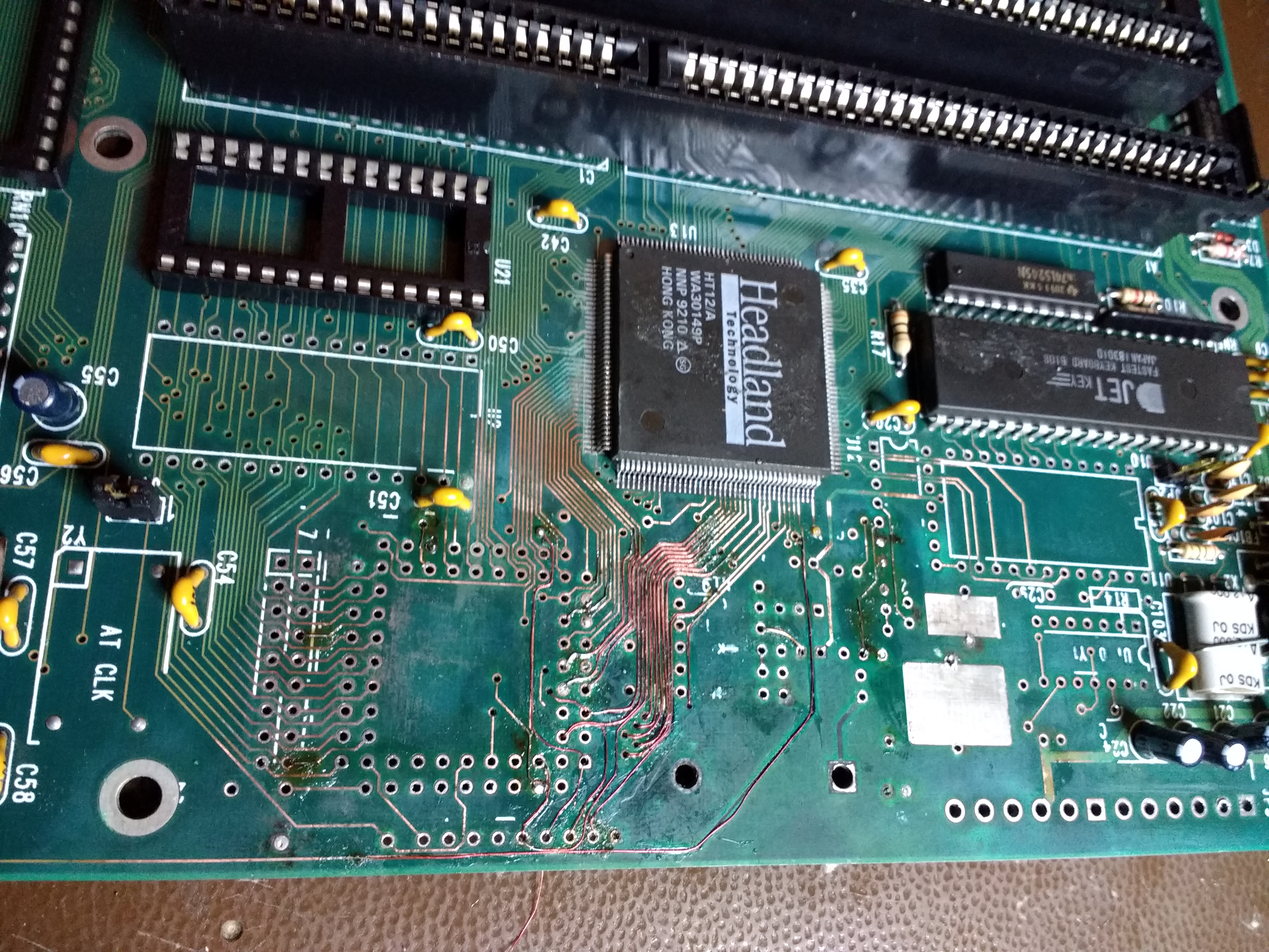
3 ) Cleaning the printed circuit.
[+] Vinegar, toothbrush and sandpaper 1000
The circuit must be completely cleaned up to highlight the copper of the tracks
and pitches.
You will do several passes with vinegar, and antioxidant and a toothbrush,
with subsequent washing with soap and water.
The most delicate phase is the one in which fine 1000 sandpaper must be used, without using
too much force and uniformly the tracks are cleaned from what remains of the protection.
When you start to see the copper, you stop and take a good picture of everything
soaked with isopropyl alcohol (makes the tracks more visible).
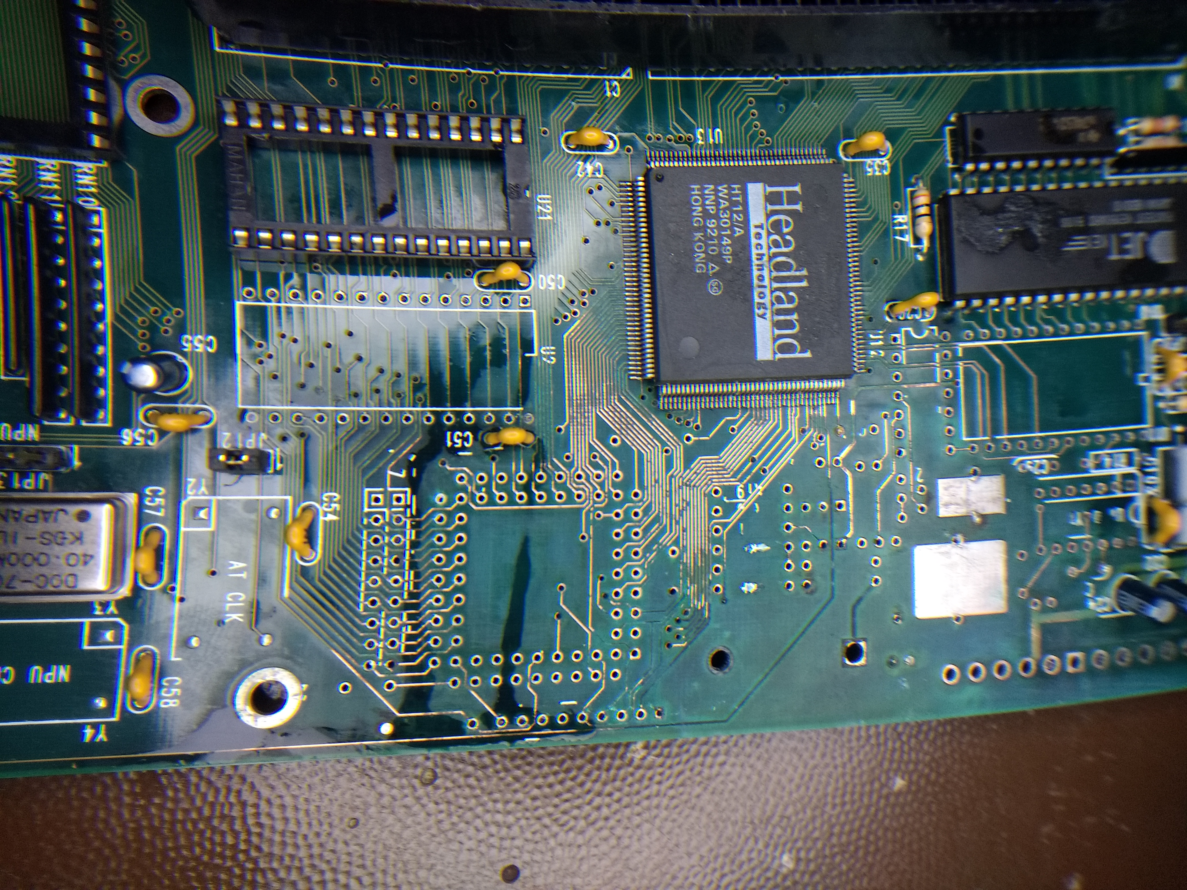
4 ) Reconstruction of the circuit
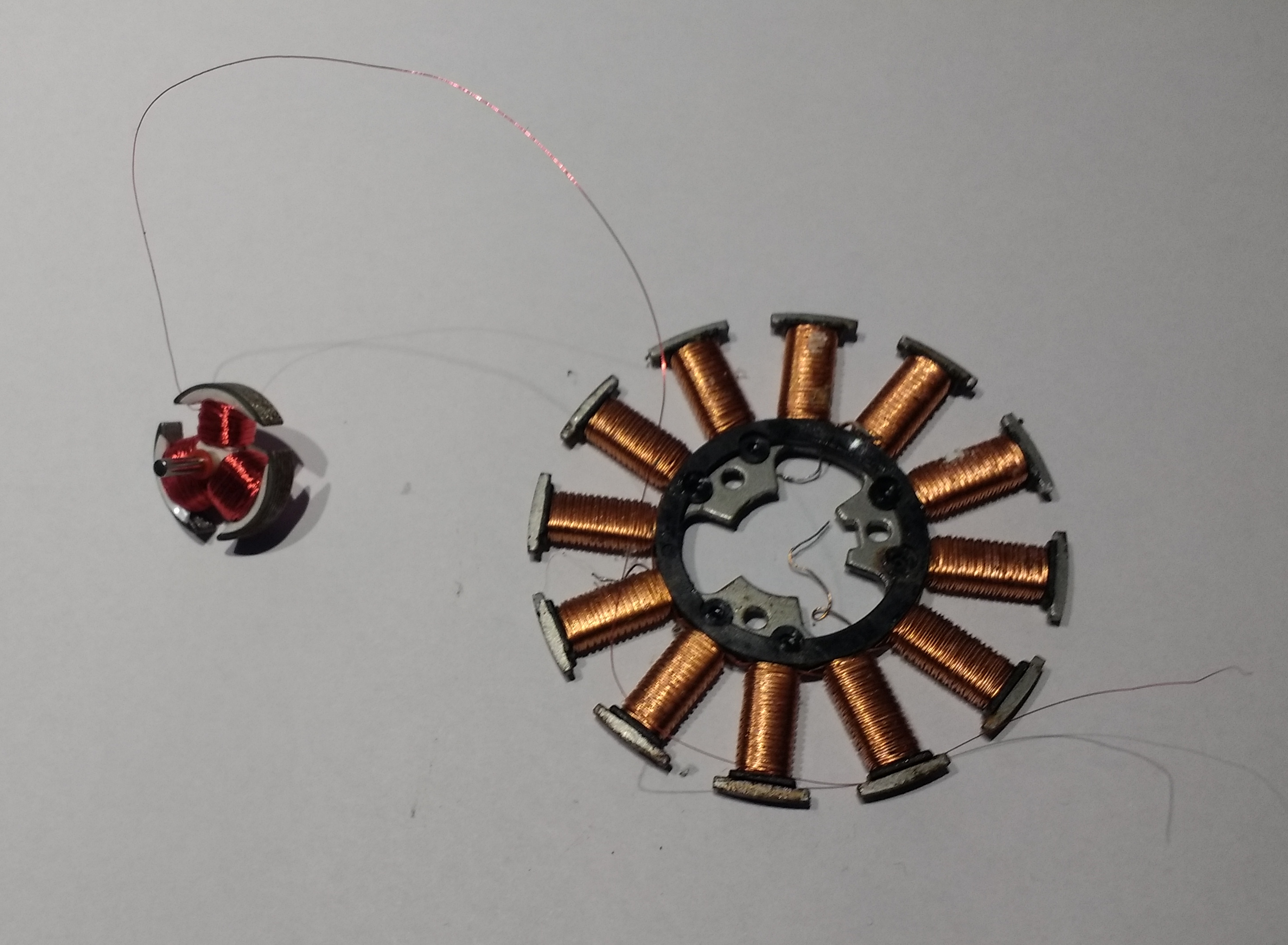
[+] Don't buy expensive wire to redo the tracks,
Remove the motor from a failed floppy and from some DVD player by recovering the motor wires
and you will have what you need in a convenient reel.
The advantage of using these wires is that they are protected with an insulating layer.
To be able to weld them you just need to place the soldering iron on the tip and wait a few seconds with tin.
The track to be rebuilt must be wet with flux, tinned delicately and then we lean on the wire that we have tinned to always weld it gently, you must not be in a hurry you can help yourself with tape to hold the wire still.
Fixed the wire on one side, proceed with attack glue and with the help of tweezers we will glue the wire on the damaged track, until we reach the other end of the track to join it or in the case of a joint on the pitch, prepare the tin wire and leave it in the hole.
5 ) Test Connections
[+] Everything will look okay but one is always missing.
Check with the tester all the tracks thus reconstructed
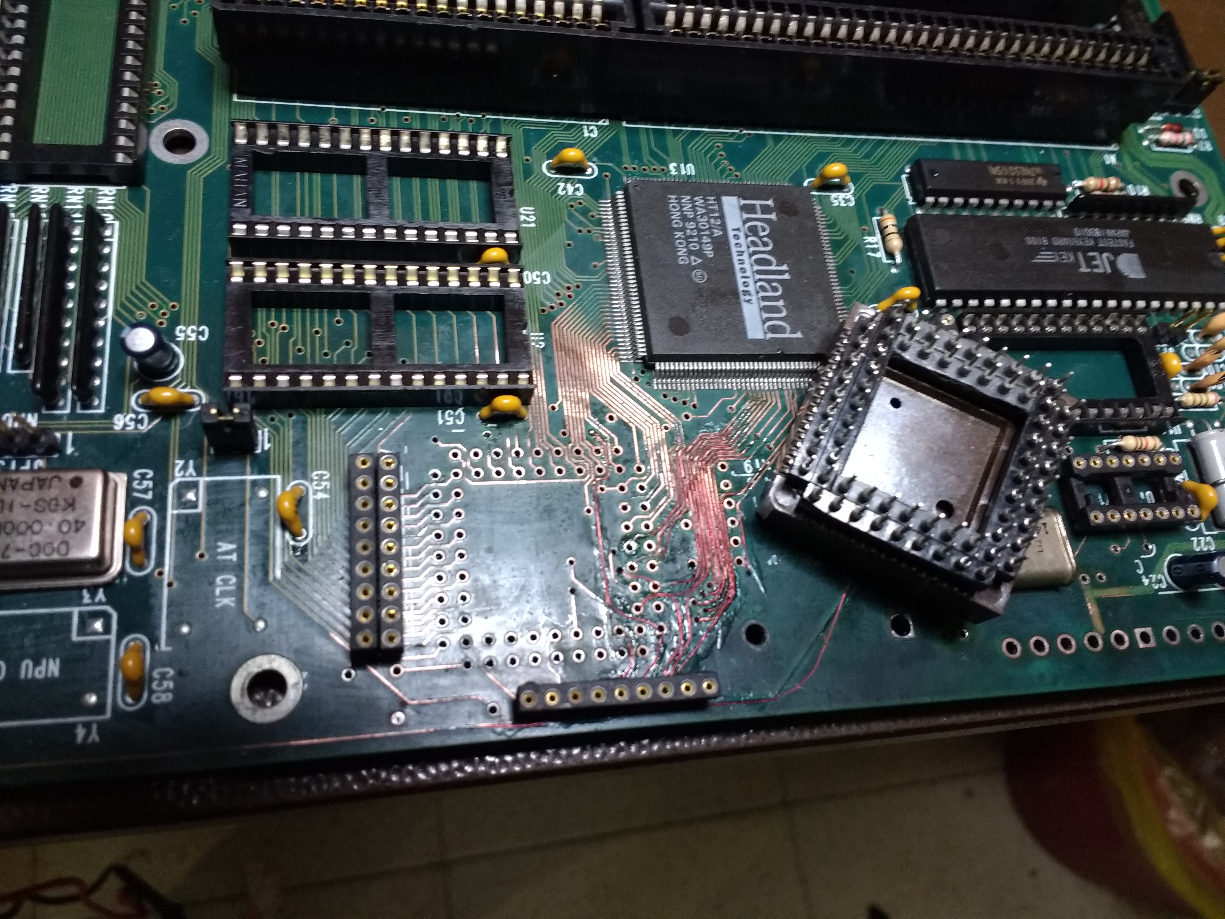
6 ) Component assembly
[+] All components possibly new
Solder in order:
Resistors, Diodes
Integrated circuit sockets (Better if tulip shaped)
Capacitors
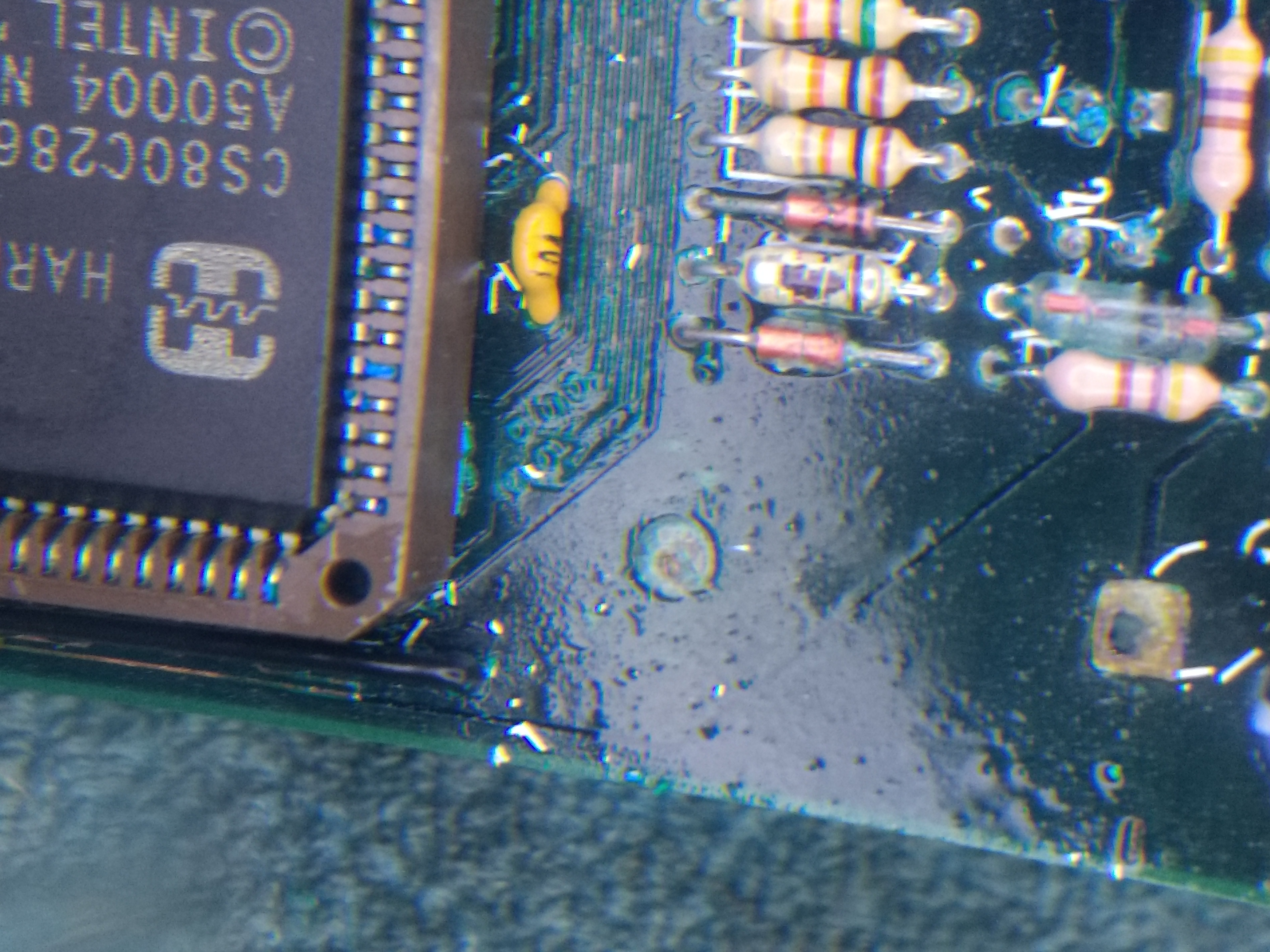
In the case of 80286 I built a socket with streep lines this because if something went wrong I would only have to unsolder 7/11 pins against 68.
7 ) Test of connections
[+] Everything will look okay but one is always missing.
Check with the tester all the tracks thus reconstructed, concentrating above all on those that end in the integrated fields.
8 ) Power on and check
[+] Magical moment but surely ... Everything will seem ok but one is always missing.
If something does not come back to you, retrieve all the available information on the internet,
photos, manuals, position of the jumpers on UH19 you will already find a lot of files
motherboards with relative configurations (http://www.win3x.org/uh19/)
Debug with the help of an ISA card that reads the POST messages of the motherboard during boot.
Useful tool but remember that it does not say exactly what the problem is, in the case of the MAT286 being repaired the boot stopped with a value of "10" and 3 short beeps which translated would mean RAM problems, in reality it was the reconstructed track A15 of the processor that did not it was connected.
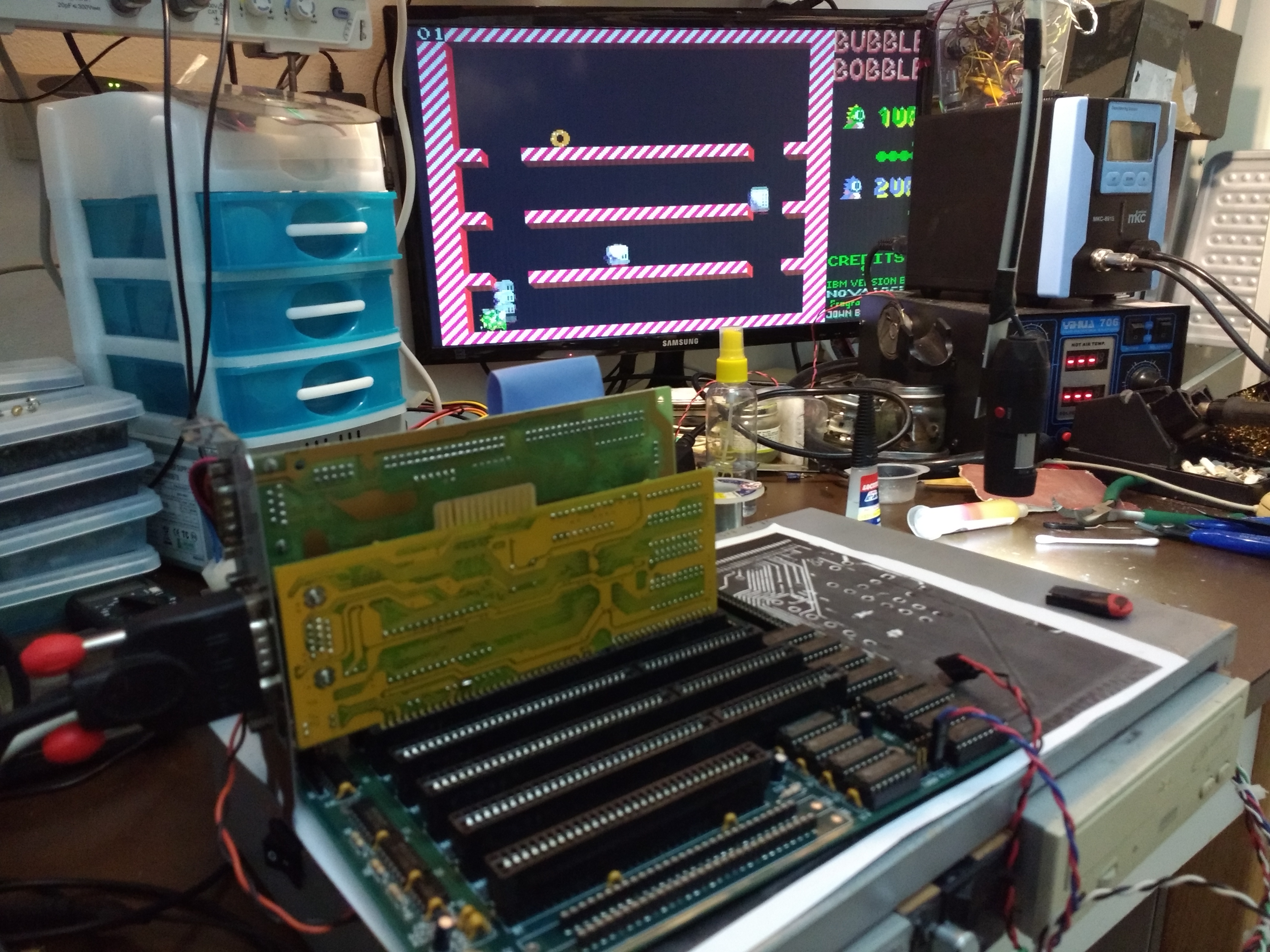
9 ) Let's play a game of Bubble Bubble
[+] Gratification needed after hard work
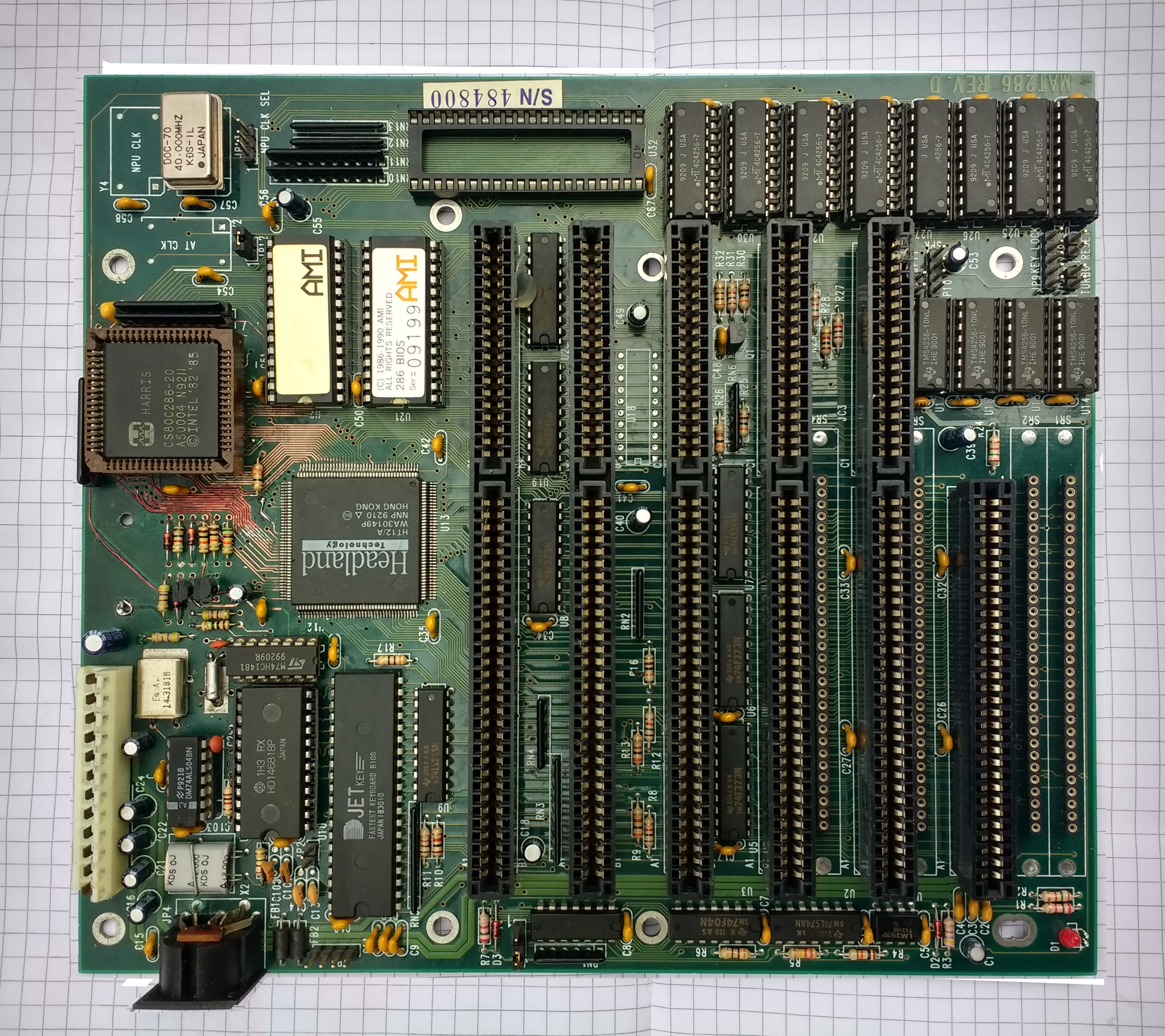
10 ) Take a nice photo
[+] Dump the bios
Upload of the beautiful photo and bios on http://www.win3x.org/uh19/ for future reference
To protect the circuit, treat the part of the exposed copper tracks with a transparent varnish and allow to dry for one or two days