BLockOUT wrote on 2021-05-04, 18:54:
[...]
hey dion
you nailed it, seems that you have a lot of experience on ps/1 2168 systems?
Not really, my mother had a very late Pentium version in her Aptiva 25 years ago, but I wasn't allowed to touch its insides. And I have a slightly different 2168 board here with IBM/Cyrix Blue Lightning DX2 on it. But the rest is just general knowledge of 486 systems and guesswork.
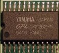
-Here are some pictures of my motherboard. i included a picture of the crystal that is near the CPU. ( i have no clue of what is he mhz of that crystal.)
It says "143xxxx", so that's 14.318MHz, which sets the clock for everything on the board except CPU, VLB and RAM. If you're in luck, there's another crystal in there somewhere which will have "25" on it. If not, then there's a PLL chip that derives 25MHz from the 14.318MHz output.
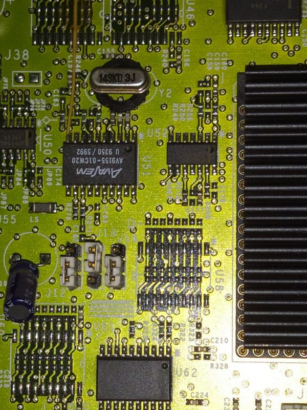
And... it's the PLL. That av9155-01cw20 chip next to the crystal is a "Low Cost 20-Pin Frequency Generator", with decscription: "The device uses a 14.318 MHz crystal to generate the CPU and all peripheral clocks for integrated desktop motherboards."
In that case you can't replace the crystal for a faster one, as that will utterly mess up the timing of all I/O depending on that clock (FDD and HDD will cease to work for starters).
But all is not lost. If I look at the datasheet for that chip, I see it's configurable using pins 19 and 20 for FS1 and FS0. Relevantly it has an internal pull-up, so either a pin is connected to GND (for logical 0) or not connected at all (for logical 1).
1. not sure if i should try to buy a new crystal for higher cpus., if i have to, what kind of crystal should i buy? any specific link to the product i would really appreciate, does it have to say "66.0 mhz"?
No, the DX/2 isn't called /2 for no reason. It has a 2x internal clock multiplier, so internally it runs at 50 or 66MHz, but externally it communicates at 25 or 33MHz. You want to bump 25MHz up to 33MHz.
Now, 25MHz CPU speed has FS1 and FS0 both set to 0; 33MHz has FS1 set to 0 and FS0 set to 1. So what you need to do is to get that FS0 pin 20 set to 1.
If I'm right about open = high and closed = low, that means that it's currently connected to ground. If so, sever that connection (de-solder/cut the leg) and you increase CPU bus clock to 33MHz. If I'm wrong it's marginally more complex, but still very doable: in that case neither pin 19 or 20 are currently connected to anything and all you need to do is to connect pin 20 to GND. Anything connected to GND will do; pin 15 on the PLL for example, but you can use anything else, up to and including the GND pin on any header. An advantage to the latter is that you can include a switch so you can switch between 25 and 33MHz at will. You can also add a switch in between in the first case (leg is now connected) for the same purpose.
You can even switch it on the fly, as the datasheet says:
Frequency Transitions - A key feature of the AV9155 is its ability to provide smooth,glitch-free frequency transitions on the CPU and 2XCPU clockswhen the frequency select pins are changed.
Now, your pic of the oscillator crystal is great, but only captures half the PLL, the relevant pins are of course (Murphy...) just out of frame. The second pic shows all the chip, but not in enough detail to figure out if 19 and 20 are connected to anything or not. If you could make a close-up of the side not on your first pic (i.e. the side opposite the one where the yellow bodge wire is connected) we can take a look for you.
But before going down this path, have you checked what J50 does? I wouldn't be at all surprised if that connects FS0 on the PLL to GND (or not if open).
2. So ..it is safe to try with a 486 overdrive 100 ?
what jumper settings should i choose for J25, j31 and j24 ? before putting one of those on the board? since that would be out of the manual im not sure what jumpers to move I have 2 overdrive 100, i tend not to use them because they get extremely hot to touch, but if it works i will put a nice 80mm fan sending air to the overdrive heatsink directly
The key to Intel Overdrives is that they are exact drop-in replacements for the original CPUs, in this case i486DX or i486DX/2 CPUs. So leave jumpers exactly as they are and if it's going to work, it will work at 75MHz now, and 100MHz if you get the clock up to 33MHz.
My machine is a 2168 and the model is L88[/u] and the sticker says its a 50mhz cpu.
It works perfectly. I had forgot that the vga output of ps/1 has one of the pins sealed, i had to install a trident isa card, and flip the vga jumper to onboard disable, then edit some inis in win3.1 so it botted really nice and im able to use windows 3.1
That 'sealed' pin is perfectly normal for old VGA without DCC:
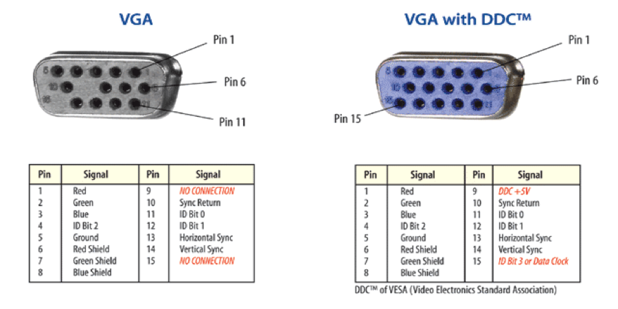
But if your monitor requires DCC, you need the card. In any event it should work fine the way you have done it.
The good thing about this pc is that the hard drive is intact, and it has the original software for win3.1 ps/1 demos,and also […]
Show full quote
The good thing about this pc is that the hard drive is intact, and it has the original software for win3.1 ps/1 demos,and also the is a recovery directory in c: , full of zip files for floppy recovery.
(no clue on how these zip files work, perhaps i just need to format floppy drives and unpack those zips into floppy disks, as there was no executable in that directory.
my plan is to take out the HDD, and use one of those IDE to usb readers in order to make a full backup of the hard drive using my laptop with acronis or any other program.
and in the future i would like to install cache chips and a soundblaster16, perhaps i can just take the cache from one of my 486 dead motherboards and install the cache on this ps/1
That would give performance a very nice boost, highly recommended.