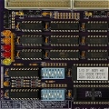
Video DRAM (and other DRAM as well) have /RAS and /CAS lines that are used to constantly refresh the contents of the memory cells. The tracks between the memory controller and the individual memory chips act like high-speed transmission lines. Furthermore, memory chips row and column strobe signals can be connected in parallel (such as the case of EXCELGRAPH and many other designs). DRAM chips have a specific capacitive loading rating so you somehow need to calculate and take into consideration the distributed capacitance and inductance of that transmission line.
Long story short, using dampening series resistors will reduce undershoot (viewable on a high-speed oscilloscope screen) of the /RAS and /CAS signals. Also the resistors will minimize signal reflections and will improve overall stability of the DRAM system.
Now the fact is that these dampening resistors should be between 10 R to 33 R or whatever small value results from the calculus.
Apparently the ISSI memories that I used, don't like values so small. And I haven't investigated why. I do have a high-speed 500 MHz bandwidth oscilloscope but I wasn't really interested into what's happening there. Once I experimentally found out that increasing these values by a 10th order and seeing everything works fine, I lost interest into troubleshooting the initial design (where I used 33 R resistors).
The artifacts are described as merely entire groups of pixel data that gets corrupted. The CRT screen will either ignite these pixels all white or they will have random colors based on the corrupted memory data.
Once I increased the dampening resistors to about 60 R, the artifacts were present only on repetitive vertical lines of the CRT screen.
Going even further to about 150 R, the artifacts reduced drastically and appeared only in certain cases, with games that had weird timings or weird video RAM control techniques.
Take this video for instance, at time 2.25 where DOOM demo begins, the CRT randomly ignites yellow pixels. In fact they are not that randomly ignited. They are part of the memory bank controlled by /CAS2, /CAS3, /CAS6, /CAS7, and /RASB signals and they appear on individual parallel vertical lines on the CRT -- even though that is not visible at the first glance.
There are some other games such as Duke Nukem 2 or Commander Keen (all series) that present weird faulty pixels but only in the High Scores and the Main Menu screens.
Otherwise they're good to go.
Even though the datasheet specifies DRAM speeds of 50 ns or better, in the end, I believe the ET4000/W32i controller was not meant to be used with DRAM chips that fast (35 ns). Or I overlooked the ISSI datasheet (honestly I haven't inspected the timing diagrams anyway, I was mainly interested into the physical connections and if I am able to drastically reduce chip count to still have 2 Mb of memory in interleave mode).
Hope this sheds some light.
TX486DLC / 40 MHz | 32 Mb RAM | 16-bit ISA Backplane | EXCELGRAPH ET4000/W32i 2 Mb | I/O Interface | Audio Interface | PC Speaker Driver | Signal View Interface
3.5" & 5.25" FDD | 4 x 512 Mb CF | HP 82341D Interface | Intel EtherExpress 16