VOGONS


First post, by polpo

User metadata
Rank Member
Rank
Member

I recently got this super clean 286 motherboard with an ACT A27C001 chipset and am having great difficulty getting it to boot. I have a feeling it's due to memory configuration, and I can't find any information about it, let alone documentation for jumper settings. It has 8 30-pin SIMM slots and a number of DIP memory sockets as well, and all were empty when I got the board. One of the retaining clips on the SIMM slots is broken and I see some wear on the DIP sockets, so it's possible both could have been populated. I have a collection of 256Kx9 and 1Mx9 SIMMs, and using either the 256K or 1M SIMMs in various configurations always results in no video and a beep code of 3 short beeps, Base 64K memory failure. I'd appreciate any help I can get to configure this board.

Identifying text:
35-2454-01 - on front of board between ISA slots. The 35- prefix is a clue that it's made by Leading Technology/PCPartner/Laser/VTech.
702356C - on front of board between ISA slots and in metal layer on front and back of PCB.
12_286MX - sticker on side of last ISA slot.
LTI QC OK - sticker on side of last ISA slot. Another pointer to it being a Leading Technology board.

I've found a lot of Leading Technology, PCPartner, and Laser 286 boards that are similar, but none are a close match.
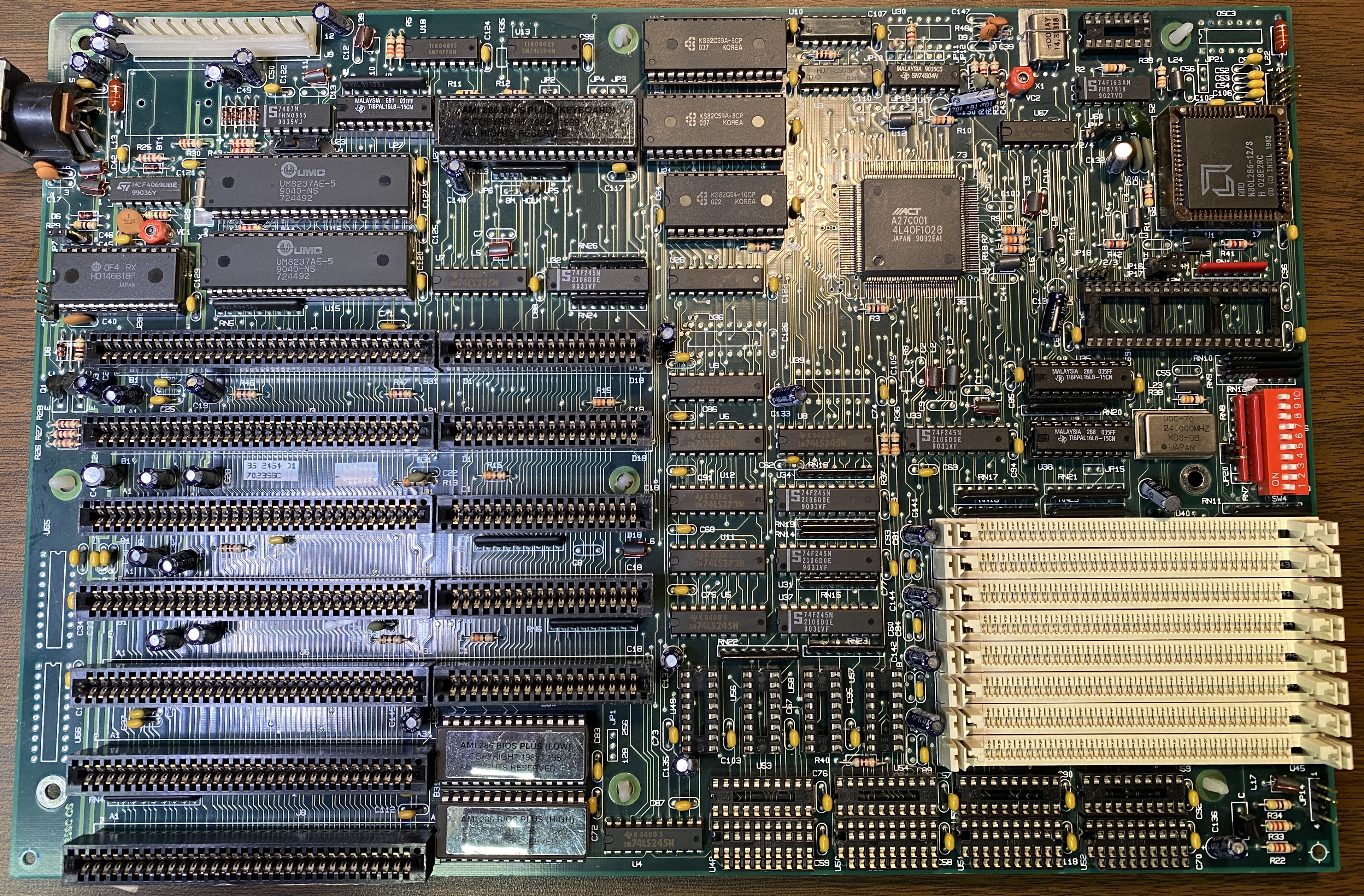
35-2454-01.jpg

I have a feeling the block of DIP switches is the key to configuring the memory for this board. It's marked with several groups: 640, DX, FS, 0WS, and RS. I've tried every combination for each group, but not every possibility for every single switch as I'm not patient enough to try 2^10 combinations. It's likely I haven't stumbled on the right one).
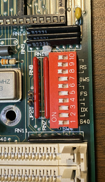
35-2454-01_dipswitches-sm.jpg

I have no idea what RS or FS could stand for, but DX may stand for "deluxe". I found this other Laser 286 board that has both DIP and SIMM ram, and there are switch settings for the "deluxe system" which used SIMMs alone for the RAM. I've tried with them both in the on position with no apparent effect. I also belive that the "640" switch corresponds to the SW2/1 setting for this board.

I've dumped the AMI BIOS for this board and got it to boot in PCem, so that 100% confirms it's a Leading Technology board, with the BIOS ID DAMI-3601-043089-K0. I've attached the BIOS and strings extracted from the bios for any other identifying marks.
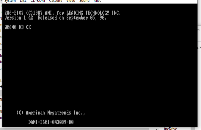
35-2454-01_post.png

creator of PicoGUS and PicoIDE

Reply 1 of 3, by weedeewee

User metadata
Rank l33t
Rank
l33t

if it behaves anything like the 5170 board I got, that wouldn't boot nor beep without a battery attached.

Right to repair is fundamental. You own it, you're allowed to fix it.
How To Ask Questions The Smart Way
Do not ask Why !
https://www.vogonswiki.com/index.php/Serial_port

Reply 2 of 3, by polpo

User metadata
Rank Member
Rank
Member

Good idea, I hadn’t tried it with a battery connected. Unfortunately it still gives the same 3 beeps with one. Thanks to the board manufacturer for clearly labeling the external battery connector as 6V, unlike the labels on the rest of the board…

creator of PicoGUS and PicoIDE

Reply 3 of 3, by SirAngelbane

User metadata
Rank Newbie
Rank
Newbie

I know this is a really old post...
But I got this board in a Leading Technology - Laser 286/2x today and it was pristine ... with disks and manual.

I am entering the text as it is in the manual, except what is in parentheses , even if the grammar is a little off.

Switch 1 : 640
When 64K x 4 bit Ram is used in Bank 1, this switch must be OFF otherwise it must be on
(Mine was on and the machine is populated with 256K x 4 so the switch was on)

Switch 2 and 3: DX
These two switches operate in pair.
In Economic system both switches set to On.
In Deluxe system both switches set to OFF
(Mine has them both on)

Switch 4, 5, 6, and 7 : FS and 0WS
These switches are reserved for factory set.
They are set as the followings:
(Image with 4 on, 5 off, 6 on, 7 off)

Important: Do not change the factory setting, else, it may slow down the system performance or even make the system malfunction.

For some special adaptors that required to be operated at 8MHZ with one wait state, such as the old IBM Token-Ring adaptor, set switch 7 to ON position and change the computer to low speed mode.

Switch 8, 9, and 10 : RS
These switches are used to set the RAM size as follows :
a) Economic system:
| Bank 0 | Bank 1 |256k type | switch
| | | SIMM RAM | 8 |9 | 10
| * | - | - | ON | ON | ON
| * | * | - | ON | ON | Off
| * | * | Slot 1 to 2 | ON | Off | ON
| * | * | Slot 1 to 4 | ON | Off | Off
| * | * | Slot 1 to 6 | Off | ON | ON
| * | * | Slot 1 to 8 | Off | ON | Off

a) Deluxe system:
| Bank 0 | Bank 1 | 1M type | switch
| | | SIMM RAM | 8 | 9 | 10
| - | - | Slot 1 to 2 | ON | ON | ON
| - | - | Slot 1 to 4 | ON | ON | Off
| - | - | Slot 1 to 6 | ON | Off | ON
| - | - | Slot 1 to 8 | ON | Off | Off
Remarks:
Bank 0 and Bank 1 must be empty

* Denotes RAM Chips installed
- Denotes socket empty