First post, by tomcattech

tomcattech
Offline
Rank
Member
- Rank
- Member
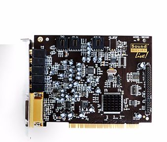
So I'm trying to get my case's headphone jack connected to the monstrous 40 pin header on the Soundblaster Live: SB0060

I've got a standard AC97 pinout going to the front of my case:
Correct me if I'm wrong but to just get the headphone jack to work I should need: Headphone Left Signal, Headphone Right Signal, Ground
I've identified the correct wires via the AC97 but the pinout on the SB060 has me stumped.... there is only "General Purpose Outputs"
GP00
GP01
GP02
Any ideas here?
I've got the requisite spare headers, pins and ribbon cable to make it work... just figuring out logistics at this point.
Any assistance would be appreciated.... Thanks!