CJ Grass wrote on 2026-03-17, 20:14:Hey,
I have a case like the one in the photo:
https://a.allegroimg.com/original/110f18/3e034aaa48c2941c6d59e9247e3a/Obudowa-MIDI […]
Show full quote
Hey,
I have a case like the one in the photo:

Currently, the display shows 133 and does not change when I press Turbo.
On the other side of the display, I have the jumpers set as follows:
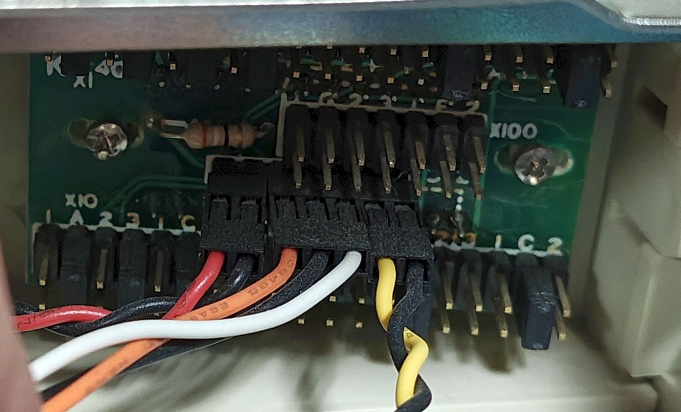
You can see three rows here (viewed from the bottom) – X10, X100 and X1. X10 and X1 each have 38 (2x19) pins, and X100 has 14 pins (2x7)
Do you have any idea how this might be configured?
The jumpers on the X10 and X1 are in the same positions, so I assume they are set to ‘3’ (133), meaning these positions should be ‘0’; however, when I press Turbo, it should be 033 (but the display doesn’t respond here), yet the machine slows down, so the Turbo function itself is working.
My components are AMD DX4-100(SV8B), Biostar MB-8433/40 UUC-A Ver:3.1.
Thank you!
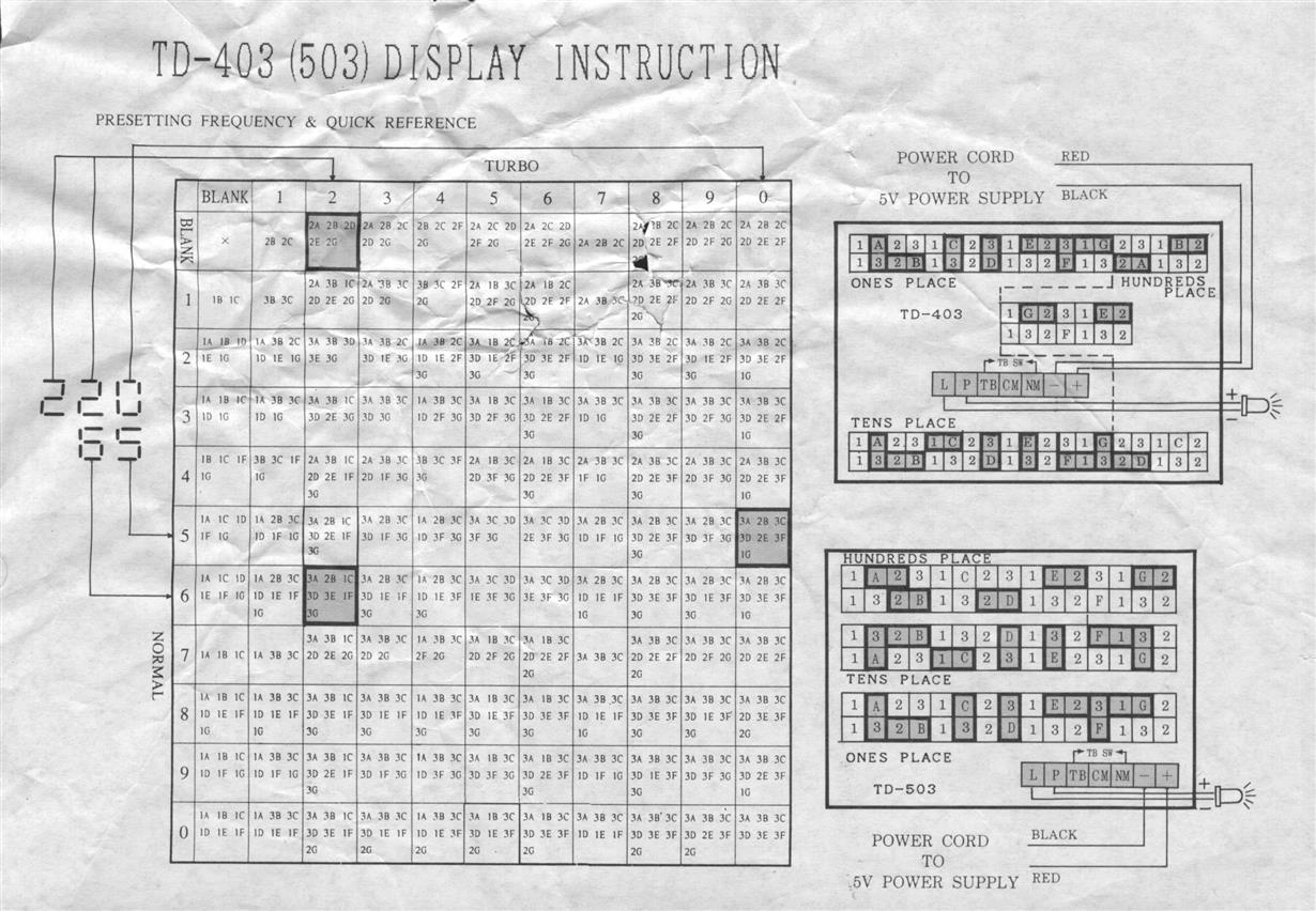
It should be the upper right diagram:
https://www.minuszerodegrees.net/led_speed_di … nd%20TD-503.jpg
The rows are subdivided in a strange way - X1 and X10 are the most of the left of the top and bottom rows. X100 is all of the center, and a some of the right of the top/bottom.
You are configuring each individual segment (the letter pins) of each digit with the jumpers. Jumper each letter according to when that segment should be lit - only for non-turbo (2), only for turbo (1), lit for both (3) or always unlit (remove jumper).
You may have to check where the connection wires go. Most of this type I have seen have the 3-pin connected to the a DPDT turbo switch. Some case types didn't use that method, and requires passing thru connections to the turbo switch and/or LED connection to the motherboard, and sometimes that takes some effort to sort out.
