First post, by GeorgeMan
- Rank
- Oldbie
Hello everyone!
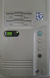
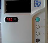
Tomorrow I'll be receiving my new AT hardware from someone who is also a VOGONer, but I had a cosmetic problem. The LED MHz indicator in my AT case's front panel could show only up to 199MHz, but the hardware I'm receiving includes a PIII 750MHz (yes at an AT mobo!). So I thought I'd change it.
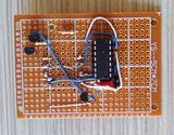
After some searching, I bought from ebay a common anode 3 digit LED 7segment display. I found out that the inputs were multiplexed, so if I wanted to show different numbers in each digit, I must configure the 1st digit, light it up, reconfigure the 2nd, light up the 2nd and so on, very fast. So I designed a circuit involving a Microchip's PIC microcontroller and some transistors/resistors, programmed it and here I am to show you the results!
Click at the pics please.
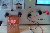
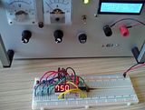
The circuit at prototyping stage. At the back is my hand made 0-30V 0-3A configurable voltage and current limit PSU 😉:
How it works
The microcontroller sets up and displays the 1st digit, lights it down, configures the 2nd and lights it etc... This procedure cycles 500 times per second for each digit, each digit lights up 2 milliseconds after the previous for ultra smooth result. The program is very small (literally only some I/O procedure takes place) and consumes about 3% of the available RAM and 2% of the available ROM of the PIC 16F688 I used.
Cost? I had the resistors, PCB, prototyping board, cables, soldering iron, PNP transistors and the PSU, so it cost me only the LED display (2 euros) and 1 day for research, prototyping and soldering.
Do you like it? 😀
Acer Helios Neo 16 | i7-13700HX | 64G DDR5 | RTX 4070M | 32" AOC 75Hz 2K IPS + 17" DEC CRT 1024x768 @ 85Hz
Win11 + Virtualization => Emudeck @consoles | pcem @DOS~Win95 | Virtualbox @Win98SE & softGPU | VMware @2K&XP | ΕΧΟDΟS
