VOGONS


First post, by Brickpad

User metadata
Rank Member
Rank
Member

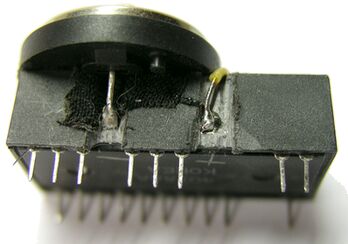
Hello everyone! So my latest Ebay purchase is a minty-fresh generic PC with a Biostar MB-8433UUD-A ver:2 and Cyrix 5x86. I was well aware before purchasing that it has a dreaded ODIN RTC on board. Having already tried to de-solder an RTC and severing a hair-thin trace on another motherboard, I decided to do a little research to see if there were any options besides tearing into the RTC itself or risk destroying another board. What I found is that there is an option for an external battery, however there is no header soldered to the motherboard, but the manual does state that JP42 can do one of three things - normal RTC operation (Pins 1+2), clear RTC (Pins 3+4), and external battery select (Pins 1+4). So, instead of going through all the trouble and risk of desoldering / soldering the RTC, why not just solder on a 4pin header instead? But before I do, is there anything I should be aware of, or perhaps something else that needs to be done before I solder a header onto the board?

This is what the board looks like: (Phil, I'm borrowing your thread for a moment.)
Biostar MB-8433UUD-A

Thanks!

Reply 1 of 15, by Skyscraper

User metadata
Rank l33t
Rank
l33t

I think you still need to desolder the RTC and replace it with one that dosnt have the battery pins bent upwards inside the Odin/Dallas package if you want to use an external battery without modifying the RTC?

The best method if you dont want to delsolder the RTC is probably to just hack away at the rather soft resin until you can access the two RTC pins that are bent upwards and just add two wires there.

New PC: i9 12900K @5GHz all cores @1.2v. MSI PRO Z690-A. 32GB DDR4 3600 CL14. 3070Ti.
Old PC: Dual Xeon X5690@4.6GHz, EVGA SR-2, 48GB DDR3R@2000MHz, Intel X25-M. GTX 980ti.
Older PC: K6-3+ 400@600MHz, PC-Chips M577, 256MB SDRAM, AWE64, Voodoo Banshee.

Reply 2 of 15, by feipoa

User metadata
Rank l33t++
Rank
l33t++

You could try to add an external battery to the RTC by grinding away the plastic and soldering on a new battery. Refer to this image,
http://www.mcamafia.de/mcapage0/jpg/8565_clock_seite.jpg

Plan your life wisely, you'll be dead before you know it.

Reply 3 of 15, by kaputnik

User metadata
Rank Oldbie
Rank
Oldbie

Perhaps not the answer you asked for or want, but even if it's possible to use an external battery without mods, I wouldn't want to leave that RTC with a dead battery just sitting there like a time bomb waiting to begin leaking or otherwise screw stuff up. I'd definitely replace the RTC. If you intend to follow the earlier advice to mod the RTC, it's probably a good idea to desolder it first aswell.

The key to desoldering through-hole stuff from the thick, often multilayered epoxy laminate used in computer mobos is to preheat the board first. Using a heat gun, I usually heat it from the back side to 130-150 deg C, keeping plastic details, electrolytic caps, etc that doesn't like heat in mind, then quickly desolder the components as usual with the soldering station on a quite high setting, say 350-400 dec C or something like that, and my trusty old desoldering pump.

An IR thermometer helps tremendeously to keep track of the temperature when preheating. Those aren't expensive today, you can find an accurate enough one below $10 at Ebay or aliexpress.com.

Reply 4 of 15, by Brickpad

User metadata
Rank Member
Rank
Member

Thanks everyone.I'll bite the bullet and order an RTC off Ebay. Not impressed that they're all from China, so I'm a bit worried they're counterfeits or NOS. Feipoa, grinding away at the chip isn't feasible as it's too close to other components. I do have a desoldering iron with a built-in hand pump, but the last time I used it to remove an RTC I borked a trace. The heat gun method might work, but again there's a lot of surface mounted components too close to that chip, so the other option is possibly using a pencil torch and pulling on one side of the chip at a time?

Reply 5 of 15, by feipoa

User metadata
Rank l33t++
Rank
l33t++

The RTC on this board is a bit tricky to desolder.

Careful of the RTC modules on eBay. They are often old, so check the datecode.

Plan your life wisely, you'll be dead before you know it.

Reply 6 of 15, by Brickpad

User metadata
Rank Member
Rank
Member

I might skip the ones on Ebay and just order one from JameCo out of California. They're only $6.95 + shipping, but I'd rather pay a few bucks more for a little extra security knowing the item is "fresh". Might order a socket along with it just in case. I am a bit nervous about desoldering the chip as I've been trying to get my hands on a decent PCI based 486 board for a while, and for a fair price.

Reply 7 of 15, by Skyscraper

User metadata
Rank l33t
Rank
l33t

Order a socket aswell so this at least will be the last time you will have to desolder the RTC.

New PC: i9 12900K @5GHz all cores @1.2v. MSI PRO Z690-A. 32GB DDR4 3600 CL14. 3070Ti.
Old PC: Dual Xeon X5690@4.6GHz, EVGA SR-2, 48GB DDR3R@2000MHz, Intel X25-M. GTX 980ti.
Older PC: K6-3+ 400@600MHz, PC-Chips M577, 256MB SDRAM, AWE64, Voodoo Banshee.

Reply 8 of 15, by kaputnik

User metadata
Rank Oldbie
Rank
Oldbie
Brickpad wrote:

Thanks everyone.I'll bite the bullet and order an RTC off Ebay. Not impressed that they're all from China, so I'm a bit worried they're counterfeits or NOS. Feipoa, grinding away at the chip isn't feasible as it's too close to other components. I do have a desoldering iron with a built-in hand pump, but the last time I used it to remove an RTC I borked a trace. The heat gun method might work, but again there's a lot of surface mounted components too close to that chip, so the other option is possibly using a pencil torch and pulling on one side of the chip at a time?

You don't have to worry about the surface mounted stuff using the method I suggested, at 130 deg C you're not even close to the melting point of the solder. Also, the components are made to withstand those temperatures, one common industrial soldering method is to position the SMD's on the PCB, and then simply heat everything in an oven until the pre-printed solder melts and joints are formed. Google "reflow soldering" if you want more details 😀

If you intend to do it the way you suggest, by melting all the joints at once and simply pull the RTC out, you'd have to work at a much higher temperature. If we assume that 63/37 leaded solder was used (which we safely can do), the melting point is ~183 deg C, and you'd probably reach higher temperatures locally, it's impossible to keep the temperature uniform with a torch. I believe it's gonna be more or less impossible to avoid melting other joints unintentionally, and well, higher temperatures of course means greater risk of breaking something else.

Reply 9 of 15, by Brickpad

User metadata
Rank Member
Rank
Member

[UPDATE]

Computer arrived today after a bit of delay, but safe and sound. As per the listing, the board did not POST, so I spent about a good hour or so looking over the jumper settings. Sure enough, either the previous owner or seller had set the RTC to CLEAR mode. After I jumpered it to the appropriate setting, the board still refused to POST or emit beep code(s). Tried swapping the RAM with different modules, but to no avail. At that point I was almost certain that the board was dead - No POST, no beeps. For reason I decided to swap out the power supplies. As luck would have it, within 5 seconds the board POSTed with the usual checksum errors after having been cleared of it settings. But the most interesting thing - no CMOS BATTERY STATE LOW error! Turns out it's still holding a charge! The fact that it was set to CLEAR might explain how it managed to survive a couple of decades without depletion; that and preserved in a heated basement.

Just to make sure it was still holding a charge, I made a couple of changes in the BIOS, and in the process noted that it managed to hold the correct day and month, except for the year, after having been powered off for so many years! After the changes I shut it down and unplugged the power supply for about 20 minutes before powering it back up. Sure enough, it was still retained the settings! 😎

After spending $50 on a hot air solder reflow station in preparation for removing the chip, I guess it won't be needed after all.

Reply 10 of 15, by feipoa

User metadata
Rank l33t++
Rank
l33t++

I haven't had a Dallas or ODIN RTC battery last more than 20 years. Soon enough you will want to prep. for the mod.

Plan your life wisely, you'll be dead before you know it.

Reply 11 of 15, by Brickpad

User metadata
Rank Member
Rank
Member

I still plan on changing it out in the near future. I have a couple of dead Dallas and ODIN RTCs I want to experiment with first to see if I can soften the epoxy resin, pop the top off, and have direct access to the battery inside. If that's the case, I won't need to desolder anything.

Reply 12 of 15, by Brickpad

User metadata
Rank Member
Rank
Member

[UPDATE]

I bought one of those Chinese S-993A desoldering guns with built-in vacuum to remove the clock chip. Had a go at it last night and all worked well except I had some trouble removing solder from MOT (pin 1) and GND (pin 12). These two holes were noticeably smaller than the rest, and appear to have no solder pads on the underside. I don't know if they were removed when I was vacuuming the solder up or they never existed in the first place. Took a me a couple of hours between desoldering, carefully reaming the pad holes clean, and installing a socket for the new chip.

Also, for those that are unaware and / or recently bought this board - Be aware that is highly important to ENABLE EDO RAM INSTALLED in the BIOS when you have EDO RAM installed, else this board will hang and / or act erratically.

Reply 13 of 15, by feipoa

User metadata
Rank l33t++
Rank
l33t++

Nice job. Even still, I do not find EDO perfectly stable on this motherboard when you are using tight timings. If you are shooting for the fastest possible with lots of RAM, FPM is the way to go.

I still do not have a desoldering gun. I looked up S-993A on eBay and noticed the cost was over $100. I wonder what the longevity of these Chinese sourced units are...

Plan your life wisely, you'll be dead before you know it.

Reply 14 of 15, by Brickpad

User metadata
Rank Member
Rank
Member
feipoa wrote:

Nice job. Even still, I do not find EDO perfectly stable on this motherboard when you are using tight timings. If you are shooting for the fastest possible with lots of RAM, FPM is the way to go.

Thanks for the heads-up. I think I'll max this out at 8MB or 16MB just like my original system. Question now is do I go with the Cyrix 5x86-100 or use the AMD 5x86 to keep it original to my original system specs? 😁

I still do not have a desoldering gun. I looked up S-993A on eBay and noticed the cost was over $100. I wonder what the longevity of these Chinese sourced units are...

For the money I think it is well worth its price. It is a surprisingly well-made "cheap" tool that has user-serviceable parts too. I believe the tips are standard size as well so they can be replaced or changed out for larger or smaller tips. There is a whole review on it on YouTube that gives a demonstration and teardown - https://www.youtube.com/watch?v=fgT9LO8lqyQ. There's also a link to get it for $95US + free shipping.

Reply 15 of 15, by feipoa

User metadata
Rank l33t++
Rank
l33t++

Go with the Cyrix if you like to tinker with CPU register settings for added advancement. There are Windows and DOS software titles which set those settings for you, so you don't need to be a programmer to get it working.

Plan your life wisely, you'll be dead before you know it.