VOGONS


Reply 40 of 50, by bitslasher

User metadata
Rank Newbie
Rank
Newbie
tehsiggi wrote on 2026-11-01, 17:22:
You have to consider complexity. If you want to be universal, it has it's price. […]
Show full quote

You have to consider complexity. If you want to be universal, it has it's price.

That's why I asked the questions on what you wanna achieve with the design. Internal or external power supply etc.

And if you want to "auto-detect" if the input are 19V instead of 12V, you'd have to have an additional step down from 19V to 12V.

If you consider this, you should directly chose 24V for the input voltage, even from the AC/DC part. Then using 19V instead is a breeze. You can then go from 24V to everything else.

Thank you for all the feedback. You know, it's funny, I originally was using 24V in my design, but sourcing the AC/DC modules seemed to be cheaper for 12V outputs, and I could then just pass the 12V through my board (less complexity/electronics). The 24V designs were for heavier industrial applications and it seemed like they knew they had deeper wallets. 😂

Can you elaborate more about the 24V base voltage and the 19V external power? If using the 24V base voltage would make the design more flexible out of the box, then I'm all for it. I hope you can tell, I'm learning here, so I'm all ears. I backed down to 12V for cost, but also it made the DC converter much simpler since it didn't have to produce the +12V rail itself, it just passes it through.

As far as complexity, I was going to try to tame/manage that by having the complex modules be as reusable as possible so that only a little extra effort would be needed to "fit" it into a new computer.

tehsiggi wrote on 2026-11-01, 17:22:
For your design: I'd go with angled connectors so the module can stand vertically. This helps to use space more efficient. Why w […]
Show full quote

For your design: I'd go with angled connectors so the module can stand vertically. This helps to use space more efficient.
Why would you go directly with the 12V into the module? Why not into the backplane and from there via the single connector to the DC/DC part?

Those pin headers are, depending on the manufacturer, rated with around 3A per pin. I'd not exceed 1,5A or 2A per pin.
Which then begs the question, how much output current do you want to transfer from the DC/DC boards per rail? 20A-30A per output voltage? (the 3.3V and 5V)
That would mean (if you go with 3A) up to 10pins per rail (when going for 30A) + 10 corresponding GND return pins per rail (because the current has to come back.

That doesn't leave much on the 40 pins.
What is your desired power rating? I've written a lot of questions in the previous posts for which we still seek answers 😉

Do you have some kicad files to review? some traces look interestingly thin 😁

Ha! I had thought about using a 90-degree connection, to allow the two boards skirt around the outside of an enclosure to improve air-flow.

The 40-pin connector I've sourced is rated to 3A per-pin. The +5v and +12v rails are pretty heavy, but spread out over many of those pins. It's a 4-layer PCB and the inner layers have a lot of copper to carry the power.

This design doesn't have any 3.3V rails. I was trying to keep the initial design simple and targeted to pre-ATX systems. From reading others' feedback, it seems that modern ATX PSUs aren't suitable anymore for original ATX systems?!? If that's the case there probably should be later revisions of this that would support 3.3V too.

The idea here is to try to create some kind of framework that things can fit together and then folks can contribute different parts. Like the DC converter I've designed at the moment would be great for AT applications and is pretty simple. It passes 12V through, and only worries about the +/-5V and -12V rails. However if folks want ATX support, who's to say that someone can't just design a new DC converter that also provides 3.3V? For example, the AT(X)Anything design referenced earlier in the thread seems totally capable of this. I haven't heard directly with it's creator yet, but it might be possible to adapt his design to this form factor? His design is really fascinating as it allows a lot of flexibility.

Another aspect is simplicity. My goal is to *try* to bring together something that is moderately approachable by beginners or light-hobbyists. So like Revenant modules can decide a lot of the minutia for the user. Like make reference designs that work for as many applications as possible. They'd be able to go somewhere like PCBWay, click "build this for me" and they just get assembled PCBs they can swap out with as little need for a soldering iron as possible.

I was waiting to push things up to GitHub until I had something working. Maybe it'd be better to just go ahead and push it up and get some feedback.

I need to tear into some of my PSUs and start making measurements for the main boards. I have my own personal favorites I want to build for myself (for various Compaq Deskpro, IBM PS/2 models), but maybe a good initial example would be to try to produce one that would fit into a wide-range of different clone/generic AT PSU form factors.

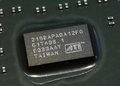
I've attached an image explaining the pinout of the connector.

Thoughts?
Reply 41 of 50, by tehsiggi

User metadata
Rank Oldbie
Rank
Oldbie
bitslasher wrote on 2026-11-01, 18:42:

Thank you for all the feedback. You know, it's funny, I originally was using 24V in my design, but sourcing the AC/DC modules seemed to be cheaper for 12V outputs, and I could then just pass the 12V through my board (less complexity/electronics). The 24V designs were for heavier industrial applications and it seemed like they knew they had deeper wallets. 😂

Can you elaborate more about the 24V base voltage and the 19V external power? If using the 24V base voltage would make the design more flexible out of the box, then I'm all for it. I hope you can tell, I'm learning here, so I'm all ears. I backed down to 12V for cost, but also it made the DC converter much simpler since it didn't have to produce the +12V rail itself, it just passes it through.

As far as complexity, I was going to try to tame/manage that by having the complex modules be as reusable as possible so that only a little extra effort would be needed to "fit" it into a new computer.

The Meanwell PSU you and I mentioned is also available with 24V instead of 12V.

The choice basically depends on what is more important for you / the design. If you want the design to be as simple (and efficient) as possible, going via DC/DC from 12V as a base voltage is the choice. You get the 12V at maximum power and the resulting other rails are as efficient as your design / the IC choice permits. But that also means that you can at max use 12V external power bricks, if you want to keep that option open.

If you want to re-use external bricks (which are typically 19V) then you need to change the topology. The 12V rail needs to be generated as well. It makes no sense then to go from 19 -> 12 -> 3.3V/5V because you'd have more load on the 12V DC/DC than you'd basically need. So you could just go on and get all voltages from the 19V directly.

Now you could/should specify everything to work with voltages from 19 - 24V. This allows you to use a large range of input devices, incl. the 200W Meanwell AC/DC PSU directly in the PSU housing. The higher input voltage allowance of 24V means you can then also feed in lower voltages. Theoretically as low as the 12V rail DC/DC permits (it has a minimal input voltage which it needs to be able to regulate the 12V).
The price is an additional DC/DC stage for the 12V and lower efficiency, because the 12V rail will now also have conversion losses which you don't have in the 12V base voltage design. Meaning: You'll get closer to 200W out of the 12V variant than from the 24V design. But at the cost of flexibility.

I've drawn you two examples:

The attachment 12V_topo.png is no longer available
The attachment 19V_topo.png is no longer available

In both cases I've added a soft-switch (as needed for ATX) just for the kicks of it.

bitslasher wrote on 2026-11-01, 18:42:

This design doesn't have any 3.3V rails. I was trying to keep the initial design simple and targeted to pre-ATX systems. From reading others' feedback, it seems that modern ATX PSUs aren't suitable anymore for original ATX systems?!? If that's the case there probably should be later revisions of this that would support 3.3V too.

The "problem" with modern PSUs is the priority of rails. Till Pentium 4, everything was focused on 5V and 3.3V with the 12V playing a minor role. That changed, so modern PSUs often just allow for combined 120W for both rails together. Which is lackluster for those older platforms. But then you'll be in the range where perhaps you want more than 200W in general. Decisions decisions.. 😉

bitslasher wrote on 2026-11-01, 18:42:

The idea here is to try to create some kind of framework that things can fit together and then folks can contribute different parts. Like the DC converter I've designed at the moment would be great for AT applications and is pretty simple. It passes 12V through, and only worries about the +/-5V and -12V rails. However if folks want ATX support, who's to say that someone can't just design a new DC converter that also provides 3.3V? For example, the AT(X)Anything design referenced earlier in the thread seems totally capable of this. I haven't heard directly with it's creator yet, but it might be possible to adapt his design to this form factor? His design is really fascinating as it allows a lot of flexibility.

Correct, but then the backplate design has to be a bit more "generic" I guess. And perhaps the common contract (aka. the connectors) have to be standardized so that all situations can be satisfied.

Which then goes back to the connector pinout and the question: How much should the individual DC/DC module provide. I'd suggest doing "major rail" modules, which can then be simple (using simple parts, easy to build, lower output power) or sophisticated (bleeding edge ICs, higher output current, more complex buildup). For the minor rails (-12V, -5V) I'd just put it either on the backplate or create a small specific DC/DC for that, with a smaller connector.

AGP Card Real Power Consumption
AGP Power monitor - diagnostic hardware tool
Graphics card repair collection

Reply 42 of 50, by rmay635703

User metadata
Rank l33t
Rank
l33t
BitWrangler wrote on 2026-10-31, 17:18:
rmay635703 wrote on 2026-10-31, 16:49:

Tons of 19.x volt laptop psus are made into waste every year, needing 12v specifically leaves a ton of donar equipment be it classic 19 volt barrel or USBC which could plug externally to fire up the internal PSU bits

The median output of those is 65W though with a lot of lower 45, even 30W ones around now. It's getting difficult to find the 95 or over 125W ones from the "Desktop replacement, also Intel can't make a decent mobile" days.

Anyway, stick that through your 20% de-efficienciser to get 12V and you're down to worrying if you'll blow things up if you run more than 2 or 3 drives.

I had a bunch of 240 watters go to e waste, classic case that the 5-15 year old pro gear goes straight into garbage instead of getting sold.

Also, my Tandy has a sub 65 watt PSU, so technically very old stuff may be usable with the stacks of ewaste going out the door, depends on the application, athlon and p4 stuff is its own ball of wax needing something beefier.

Reply 43 of 50, by BitWrangler

User metadata
Rank l33t++
Rank
l33t++

BTW I was looking around to see what the "competition" might be for a new build PSU and discovered there seems to be a stock of Antec or clone PP-300V appearing on the market all over the place, at prices ranging from $55 to LMAO. They do not seem to be showing up well on searches for AT PSU but with things like Old Style Industrial Power and P8 P9 connector.

Unicorn herding operations are proceeding, but all the totes of hens teeth and barrels of rocking horse poop give them plenty of hiding spots.

Reply 44 of 50, by MikeSG

User metadata
Rank Oldbie
Rank
Oldbie
bitslasher wrote on 2026-11-01, 18:42:

Another aspect is simplicity. My goal is to *try* to bring together something that is moderately approachable by beginners or light-hobbyists. So like Revenant modules can decide a lot of the minutia for the user. Like make reference designs that work for as many applications as possible. They'd be able to go somewhere like PCBWay, click "build this for me" and they just get assembled PCBs they can swap out with as little need for a soldering iron as possible.

I was waiting to push things up to GitHub until I had something working. Maybe it'd be better to just go ahead and push it up and get some feedback.

I need to tear into some of my PSUs and start making measurements for the main boards. I have my own personal favorites I want to build for myself (for various Compaq Deskpro, IBM PS/2 models), but maybe a good initial example would be to try to produce one that would fit into a wide-range of different clone/generic AT PSU form factors.

I'm going to sound like the devil but simplicity is one complete PCB per target product, with nothing to do or worry about. Another point is that people typically care for their vintage PCs, and only want actual OEM or better.

A standard ~200 watt PSU for a 486 delivers 10-20 amp 5v, 8-10 amp 12v. When you turn on a PC with four hard drives there's at least an 8 amp draw on the 12v line until they're up to speed. Many capacitors on the 5v line, and the CPU also draws a lot of current. The noise and huge amp draw from motors on the 12V line mean sensitive electronics should use a completely separate rail (separate 1000uF caps, regulation and overdraw protection). 1000uF caps on the PSU should fill before the motherboard switches on.

So I recommend separate 12v and 5v Mean Well PSUs. One PCB. Do all the work so hobbyists don't have to touch a PSU.

Reply 45 of 50, by bitslasher

User metadata
Rank Newbie
Rank
Newbie
MikeSG wrote on 2026-11-02, 07:50:

I'm going to sound like the devil but simplicity is one complete PCB per target product, with nothing to do or worry about. Another point is that people typically care for their vintage PCs, and only want actual OEM or better.

How is that sound like a devil? 😀 I agree about "keeping it simple" but one has to balance things out. These fab companies normally require a minimum order to fabricate PCBs. So this split design is meant to make it so the complex/expensive work is on a part that can be reused across more than one specific computer's PSU. It's much cheaper to get a 5-board order of a dumb backplane than the complex 4-layer design of the DC module.

MikeSG wrote on 2026-11-02, 07:50:

A standard ~200 watt PSU for a 486 delivers 10-20 amp 5v, 8-10 amp 12v. When you turn on a PC with four hard drives there's at least an 8 amp draw on the 12v line until they're up to speed. Many capacitors on the 5v line, and the CPU also draws a lot of current. The noise and huge amp draw from motors on the 12V line mean sensitive electronics should use a completely separate rail (separate 1000uF caps, regulation and overdraw protection). 1000uF caps on the PSU should fill before the motherboard switches on.

As far was the power ratings go, my initial design was to target the an "AT 200W" PSU. This initial design is for desktop computers with one hard drive in it, not a 4 hard drive SERVER use case. Since one of my target systems to support is the SystemPro, which can take up to 4 drives, there was plans to make use of the Mean Well 300W cousin.

The power rails of this DC converter are:

  • 200W Mean Well: +5V 20A / +12V ~6A / -5V 0.5A / -12V 1.0A
  • 300W Mean Well: +5V 20A / +12V ~14A / -5V 0.5A / -12V 1.0A
MikeSG wrote on 2026-11-02, 07:50:

So I recommend separate 12v and 5v Mean Well PSUs. One PCB. Do all the work so hobbyists don't have to touch a PSU.

So about that-- the 12V rail comes straight off the Meal Well PSU, so filtering is handled by it. The 5V, -12V, and -5V rails come off the DC module. Would that address the issue you're mentioning?

This is very good feedback I'm getting from everyone. I'm taking it all in and incorporating it as much as I can into what I'm doing.

Just to be a little more clear about what my intentions are:

First phase is to get a working "AT Desktop PSU" replacement working. My target for this was the "Generic AT 200W PSU"

Next phases would be to maybe have beefier designs that can handle "AT Server PSU" capacities. I'm looking at what that means and if that would even add much to the cost of what I'm building for far. That is-- what would it take to get up to 40A on the +5V rail?

The more I hear, there seems to also be a demand for ATX 1.0-compliant replacements as well. This would necessitate the support for a +3.3V rail. This would make it a bit more expensive to make. It seems like the person working on the AT(X)Anything power supply may have worked a lot of this out already-- and has working units! Hopefully he's still following here and can speak to this.

Reply 46 of 50, by myne

User metadata
Rank l33t
Rank
l33t

I'd still suggest usb pd.
48v usb psus are only going to get more common.

I built:
Convert old ASUS ASC boardviews to KICAD PCB!
Re: A comprehensive guide to install and play MechWarrior 2 on new versions on Windows.
Dos+Windows 3.11+tcp+vbe_svga auto-install iso template
Script to backup Win9x\ME drivers from a working install
Re: The thing no one asked for: KICAD 440bx reference schematic

Reply 47 of 50, by kingcake

User metadata
Rank Oldbie
Rank
Oldbie

No offense, but mains psu design and testing is not something a hobbyist should be doing in their basement. that's life or death. a new product from scratch requires national certification. that's why so many companies include pre-made approved supplies inside their products. if a big company can't pay for the testing a hobbyist certainly can not.

I would rather repair an old PSU, or use Meanwells as stated above than some untested thing that spits out a tremendous amount of noise. The USB PD suggestion only reinforces my thinking.

Reply 48 of 50, by myne

User metadata
Rank l33t
Rank
l33t

USB PD = tested and approved off the shelf HV AC>DC, making the PC side a simple DC-DC conversion.

I'm confused why you think that would be a big issue.

I built:
Convert old ASUS ASC boardviews to KICAD PCB!
Re: A comprehensive guide to install and play MechWarrior 2 on new versions on Windows.
Dos+Windows 3.11+tcp+vbe_svga auto-install iso template
Script to backup Win9x\ME drivers from a working install
Re: The thing no one asked for: KICAD 440bx reference schematic

Reply 49 of 50, by tehsiggi

User metadata
Rank Oldbie
Rank
Oldbie
myne wrote on 2026-11-03, 03:47:

USB PD = tested and approved off the shelf HV AC>DC, making the PC side a simple DC-DC conversion.

I'm confused why you think that would be a big issue.

I'm not seeing anyone saying that is a big issue. Rather only a question of implementation: Want AC to go into the machine like originally, PD is not an option. If you don't care about that, only limit of PD is the supplied power. And you have to make sure that every following DC/DC for the rails is capable of going to 48V, if you really wanna support PD3.2.

myne wrote on 2026-11-03, 00:25:

48v usb psus are only going to get more common.

Probably, however the uptick for the first three years hasn't been great. And the reason is understandable: What device, aside a high end notebook or big screen as a power hub would need 240W? Most devices are more than happy with the up to a 100W that PD3.1 delivers. So you can plan ahead for it in the design, but when designing something for now I wouldn't look for the hope of having something widely available in 2 years. In general I'd just see PD as an optional thing. Have the backplate work with DC input anyways, choose if you want to have a built in AC/DC part or put an external plug of any choice to it. Use an off the shelf trigger board for that. There is no need to hassle around implementing the PD Sink with an IC etc yourself if there are 2$ ready to use alternatives out there.

kingcake wrote on 2026-11-03, 01:03:

No offense, but mains psu design and testing is not something a hobbyist should be doing in their basement. that's life or death. a new product from scratch requires national certification. that's why so many companies include pre-made approved supplies inside their products. if a big company can't pay for the testing a hobbyist certainly can not.

I would rather repair an old PSU, or use Meanwells as stated above than some untested thing that spits out a tremendous amount of noise. The USB PD suggestion only reinforces my thinking.

And designing that AC/DC part is apparently also not in scope of the thread starters project, so no issues here. So there is no need to think about certifications etc. for that. You still would have to properly wire the AC part up, but I mean this is the hobbyist level anyways. I don't think repairing an SMPS as a hobbyist is less dangerous than wiring up a new PSU yourself.

bitslasher wrote on 2026-11-03, 00:14:

That is-- what would it take to get up to 40A on the +5V rail?

Not much, a beefier DC/DC converter, that's it. Same for the 3.3V rail. The ATX anything project basically let's you use off the shelf modules instead of rolling your own design, so that's how it's solved there.

Also if you go with a backplane design, consider that the current has to get from the connector of the DC/DC part to the cables. So a backplane should have:

  • Wide (multilayer) traces to support the current
  • Options to install thick wire bridges alongside the trace for increased current capability / less drop under load
  • Perhaps the option to use 2OZ copper for the traces

AGP Card Real Power Consumption
AGP Power monitor - diagnostic hardware tool
Graphics card repair collection

Reply 50 of 50, by adalbert

User metadata
Rank Oldbie
Rank
Oldbie
bitslasher wrote on 2026-11-03, 00:14:

That is-- what would it take to get up to 40A on the +5V rail?

Artesyn SIL40C2-00SADJ-VJ does 5V 40A and costs 35EUR. Though it is rated for 13.8V input max, so no PD option here and no laptop PSUs, a large 12V brick would be needed.
https://eu.mouser.com/en/ProductDetail/Advanc … pvKP4y20w%3D%3D

But there are converters like this one: EHHD024A0A41-HZ https://www.digikey.com/en/products/detail/om … 0A41-HZ/4941280
which make 5V 24A from 18V-75V input. So it is feasible for PD and other sleek modern stuff. It is on my list to experiment with one of these at some point.

AT(X)Anything: a modular DC-DC PSU for old PCs (open hardware)
Repair/electronic stuff videos: https://www.youtube.com/c/adalbertfix
ISA Wi-fi + USB in T3200SXC: https://www.youtube.com/watch?v=WX30t3lYezs