VOGONS


Corosion or Oxidisation

Topic actions

First post, by AppleSauce

User metadata
Rank Oldbie
Rank
Oldbie

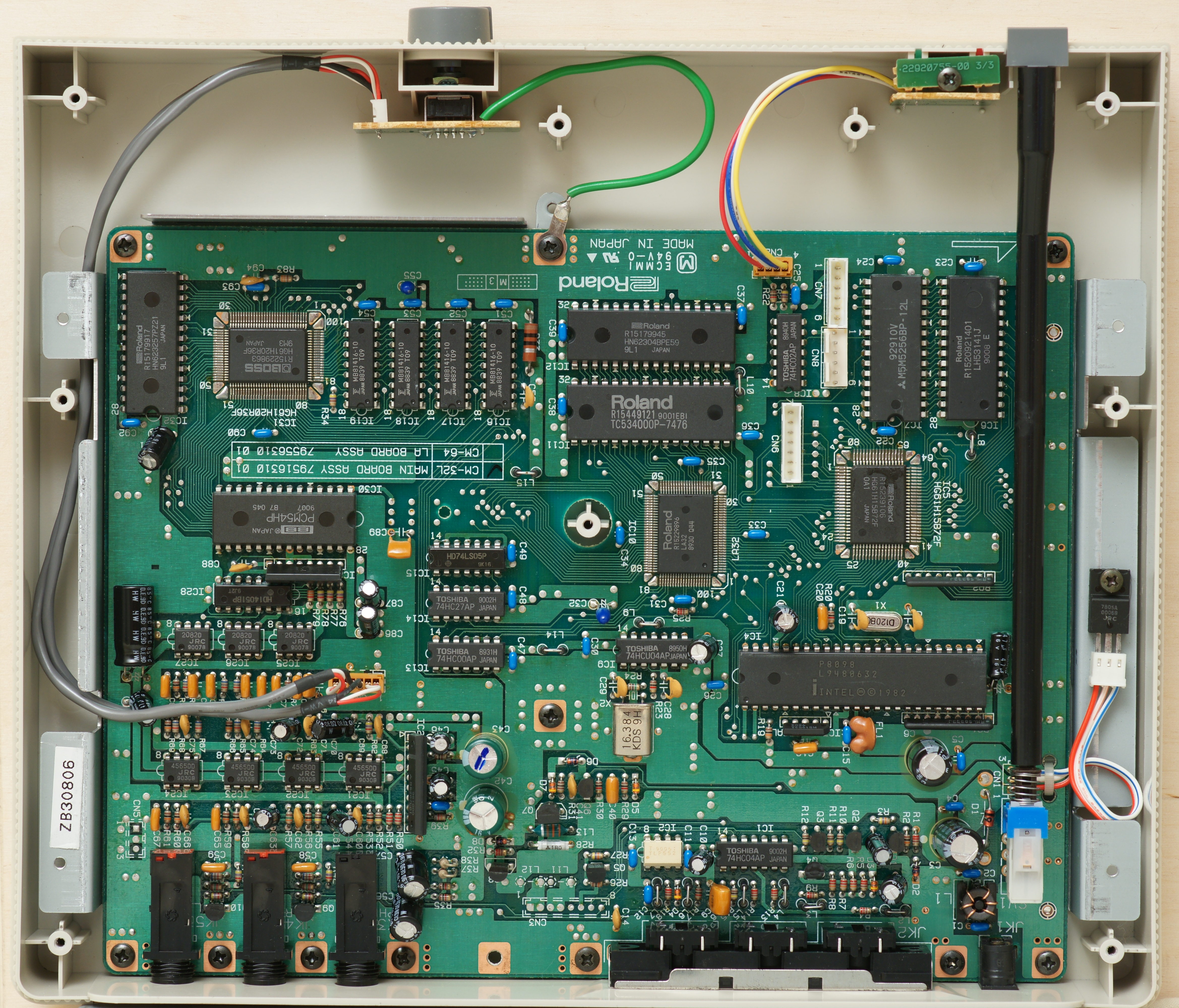
I was inspecting the motherboard of the CM32L I just got and noticed there were some discoloured parts.
Is it from flux and the glue oxidising or are the caps leaking?

Just wanna make sure before I test power it on.

The attachment 20211003_174201.jpg is no longer available
The attachment 20211003_174251.jpg is no longer available
The attachment 20211003_174149.jpg is no longer available

Reply 1 of 34, by AppleSauce

User metadata
Rank Oldbie
Rank
Oldbie

More pics

Reply 2 of 34, by chris2021

User metadata
Rank Oldbie
Rank
Oldbie

clearly it seems like liquid is escaping.

Reply 3 of 34, by vstrakh

User metadata
Rank Member
Rank
Member

Not a leakage. It should be a factory glue.
https://youtu.be/BeDKwi-GJRI?t=39

Similar glue blobs are visible on a photo of presumably working board here: http://vgmpf.com/Wiki/images/1/1d/CM-32L_-_Internal.jpg
though it didn't degrade as much.

Last edited by vstrakh on 2021-10-03, 13:10. Edited 1 time in total.

Reply 4 of 34, by AppleSauce

User metadata
Rank Oldbie
Rank
Oldbie

Welp its not powering on , the light flashes for like a split second then goes out again

Reply 5 of 34, by AppleSauce

User metadata
Rank Oldbie
Rank
Oldbie

The power jack looks pretty corroded so that might be the issue but I'm not sure

Reply 6 of 34, by AppleSauce

User metadata
Rank Oldbie
Rank
Oldbie

Here's a pic

Reply 7 of 34, by AppleSauce

User metadata
Rank Oldbie
Rank
Oldbie

Ah wait that pics kinda blurred , my bad

Reply 8 of 34, by vstrakh

User metadata
Rank Member
Rank
Member

Worth checking the voltages on the PCB side to know if the PSU is up to the task.

Reply 9 of 34, by AppleSauce

User metadata
Rank Oldbie
Rank
Oldbie

I've been using this with a stepdown , works fine for my other stuff

The attachment 20211003_211928.jpg is no longer available

Reply 10 of 34, by vstrakh

User metadata
Rank Member
Rank
Member

Either way you won't go far without a multimeter. You need to probe the voltages, connectivity, etc.

Reply 11 of 34, by Tetrium

User metadata
Rank l33t++
Rank
l33t++
AppleSauce wrote on 2021-10-03, 07:36:

More pics

It does seem like glue, especially this cap here which is mounted sideways to the PCB.

The corrosion on the connector does look kinda bad though.

Whats missing in your collections?
My retro rigs (old topic)
Interesting Vogons threads (links to Vogonswiki)
Report spammers here!

Reply 12 of 34, by weedeewee

User metadata
Rank l33t
Rank
l33t

the first photo shows some white that doesn't look kosher. the brown stuff near the solder pads is, I'm guessing, Flux residue.
The other photos where there's lots of brown stuff under the capacitors, is glue.
That barrel socket definitely has seen better days, makes one wonder what the inside contacts look like.
Anyway, plug it in, turn it on, and measure the voltages.

Right to repair is fundamental. You own it, you're allowed to fix it.
How To Ask Questions The Smart Way
Do not ask Why !
https://www.vogonswiki.com/index.php/Serial_port

Reply 13 of 34, by AppleSauce

User metadata
Rank Oldbie
Rank
Oldbie

Funnily enough my soldering iron got here today , its still pretty cheap but it has adjustable temp unlike my older ones , I'm going to try swapping the corroded jack since it seems to be the simplest thing to start with , any reccomendations on soldering temp?

Also I bought some of these jacks for fixing some other roland gear , would these be a good bet for the cm32L?

The attachment socket-21mm-pin-dc-pcb-black-dimensions.jpg is no longer available
The attachment 20211004_153504.jpg is no longer available

Reply 14 of 34, by canthearu

User metadata
Rank Oldbie
Rank
Oldbie

400 degrees C is a good starting point.

Use solder braid/wick to clear joints of solder.

Work quickly if possible. Hanging around the board with lots of heat is a good way to damage pads.
Use 60/40 leaded solder to help you rapidly install new plug. Add extra 60/40 solder to the joints if you have difficulty melting the old solder.

Reply 15 of 34, by AppleSauce

User metadata
Rank Oldbie
Rank
Oldbie

Well I just replaced the jack , I have the exact same issue so it looks like its something else

Reply 16 of 34, by AppleSauce

User metadata
Rank Oldbie
Rank
Oldbie

Okay after inspecting the board it turns out one of the caps has burst , I didn't notice it because one of the original factory workers drew an A on it , after cleaning the marker off its definitely got a cut.

The attachment 20211004_210538.jpg is no longer available
The attachment 20211003_224923.jpg is no longer available

Reply 17 of 34, by AppleSauce

User metadata
Rank Oldbie
Rank
Oldbie

So that's 3 recap jobs i need to do now, one for a abit bf6 mobo project , one for a Aopen psu and now one for a cm32L.

I'm sick of seeing burst caps at this point.
I suppose I'll just do one big bulk order from mouser and get it all out of the way. 🙁

Reply 18 of 34, by AppleSauce

User metadata
Rank Oldbie
Rank
Oldbie

Okay on second thought I can't tell of its the dye of the marker or a gap.

Reply 19 of 34, by AppleSauce

User metadata
Rank Oldbie
Rank
Oldbie

I guess I'll have to test other components, any idea on what would cause the power to cut off just after switching something on?