VOGONS


ATC-5200 + k6-2+

Topic actions

Reply 40 of 53, by Sphere478

User metadata
Rank l33t++
Rank
l33t++

Typical is
Base =2.0v
Jp1 + .1v
Jp2 + .2v
Jp3 + .4v
Jp4 + .8v

With the combo of jp1-4 you can make voltages.

This is the typical layout of many socket 7 voltage setups

Looking at your voltage manual it seems to follow this. I assume to get to 2.0v you removed all voltage jumpers?

Sphere's PCB projects.
-
Sphere’s socket 5/7 cpu collection.
-
SUCCESSFUL K6-2+ to K6-3+ Full Cache Enable Mod
-
Tyan S1564S to S1564D single to dual processor conversion (also s1563 and s1562)

Reply 42 of 53, by Sphere478

User metadata
Rank l33t++
Rank
l33t++
brunofbrsilva wrote on 2023-07-08, 21:55:

with all off or with the second one on it made no difference in the multimeter, I even found it strange, now all the other keys when turned on changed the voltage.

Maybe there is something wrong with position 2

Sphere's PCB projects.
-
Sphere’s socket 5/7 cpu collection.
-
SUCCESSFUL K6-2+ to K6-3+ Full Cache Enable Mod
-
Tyan S1564S to S1564D single to dual processor conversion (also s1563 and s1562)

Reply 43 of 53, by brunofbrsilva

User metadata
Rank Newbie
Rank
Newbie

I thought the same thing, maybe position 2 has a problem, because, as nothing changes in the on or off position, possibly it is defective.

One question, considering the age of the motherboard, do you think it would be interesting to do a recap?

Reply 44 of 53, by Sphere478

User metadata
Rank l33t++
Rank
l33t++
brunofbrsilva wrote on 2023-07-08, 22:17:

I thought the same thing, maybe position 2 has a problem, because, as nothing changes in the on or off position, possibly it is defective.

One question, considering the age of the motherboard, do you think it would be interesting to do a recap?

It isn’t a bad idea, I personally only recap boards that have problems though. As to not tempt fate. (And be lazy)

But it is true that probably all capacitors that old of the electrolytic variety have probably experienced degradation. Other types may have fared better

Sphere's PCB projects.
-
Sphere’s socket 5/7 cpu collection.
-
SUCCESSFUL K6-2+ to K6-3+ Full Cache Enable Mod
-
Tyan S1564S to S1564D single to dual processor conversion (also s1563 and s1562)

Reply 45 of 53, by Chkcpu

User metadata
Rank Member
Rank
Member
brunofbrsilva wrote on 2023-07-08, 21:38:

See if this is correct:

IMG-20230708-WA0815.jpg

Oh, I guessed wrong about the position of the Vcore controller IC. This 74F240 is a buffer IC, probably for the ISA-bus. 😉

Looking at the motherboard picture on TheRetroWeb, I see a likely candidate at the other side of the CPU socket, near the edge of the board. It has a large S like logo on top.
Can you send a close-up picture of that IC? Thanks!

Jan

CPU Identification utility
The Unofficial K6-2+ / K6-III+ page

Reply 47 of 53, by BitWrangler

User metadata
Rank l33t++
Rank
l33t++

That seems like it's gonna be a CMOS RAM to hold some settings. http://www.allparts.co.kr/pdffile/pdffile_001/735.PDF

Unicorn herding operations are proceeding, but all the totes of hens teeth and barrels of rocking horse poop give them plenty of hiding spots.

Reply 48 of 53, by BitWrangler

User metadata
Rank l33t++
Rank
l33t++

Well, found some clear-ish pic on an aliexpress listing, but still can't see the regulator IC clear enough to be sure..
https://www.aliexpress.com/item/1005004038474240.html
currently suspecting the tiny little 8 pin thing underneath the bottom toroid coil, under the CPU socket.

Unicorn herding operations are proceeding, but all the totes of hens teeth and barrels of rocking horse poop give them plenty of hiding spots.

Reply 49 of 53, by Nexxen

User metadata
Rank Oldbie
Rank
Oldbie

@bruno: can you post high resolution pictures of the board?
Users here are going continents away to find a decent pics 😀

PC#1 Pentium 233 MMX - 98SE
PC#2 PIII-1Ghz - 98SE/W2K

Reply 51 of 53, by Chkcpu

User metadata
Rank Member
Rank
Member
BitWrangler wrote on 2023-07-09, 22:14:

Well, found some clear-ish pic on an aliexpress listing, but still can't see the regulator IC clear enough to be sure..
https://www.aliexpress.com/item/1005004038474240.html
currently suspecting the tiny little 8 pin thing underneath the bottom toroid coil, under the CPU socket.

Thank you BitWrangler, I believe you found the Vcore regulator IC! 😀
Although the photo on AliExpress is from an ATC-5200 V2.0 board, which has a different lay-out than the v1.0 board of the OP, I know now that we have to look for a tiny 8-leg chip.

So enlarging the V1.0 photo from TheRetroWeb, I located the tiny regulator chip close to the SW2 Vcore dipswitches. A logical place indeed. 😉

atc-5200-front-voltage regulator.jpg
Filename
atc-5200-front-voltage regulator.jpg
File size
22.36 KiB
Views
444 views
File comment
ATC-5200 Vcore circuit
File license
Public domain

@brunofbrsilva, can you make a picture of that area so we can read the partnumber of this small 8-leg chip? With this info I can make a definitive Vcore selection table for you and for TheRetroWeb.

Thanks, Jan

CPU Identification utility
The Unofficial K6-2+ / K6-III+ page

Reply 53 of 53, by Chkcpu

User metadata
Rank Member
Rank
Member
brunofbrsilva wrote on 2023-07-18, 22:35:

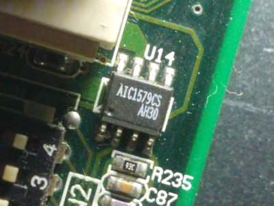
Good night everyone, sorry for the delay here is the photo:

16897196315287856556357238702384.jpg

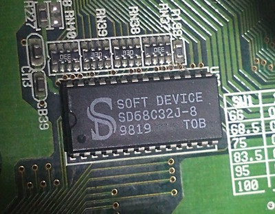
Thanks for the clear picture, yes this is the Vcore regulator we were searching for! 😀
However it is not the fancy regulator we were expecting. This AIC1579 is a simple step-down controller with a single feedback input. It uses an external resistor network on the motherboard to make other voltages than the base 2.0V.
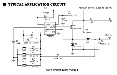
This is the typical schematic from the datasheet:

AIC1579 schematic.png
Filename
AIC1579 schematic.png
File size
92.04 KiB
Views
398 views
File license
Public domain

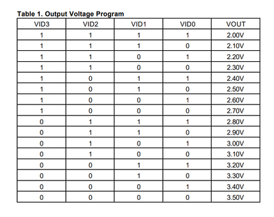
So the values of the resistors connected to the 4 VID switches determine the selectable output voltage. With the resistor values from the schematic, you will get these possible output voltages:

Output Voltages.png
Filename
Output Voltages.png
File size
50.94 KiB
Views
398 views
File license
Public domain

But we now know that the base voltage of this regulator is 2.0V and that you should set all four SW2 dipswitches to OFF to get this voltage for your K6-2+ CPU! 😉

Here is the complete AIC1579 datasheet:

Filename
AIC1579.pdf
File size
171.77 KiB
Downloads
24 downloads
File comment
AIC1579 datasheet
File license
Public domain
Karbist wrote on 2023-07-10, 11:01:

https://datasheetspdf.com/pdf/136498/AnalogIn … ation/AIC1579/1

I got 2.0v on vcore with all 4 dip switches set to off.

@Karbist, thanks for the datasheet. You also found this regulator chip on your board.
Great that you could confirm the 2.0V Vcore with all 4 dipswitches off. 😀

Jan

CPU Identification utility
The Unofficial K6-2+ / K6-III+ page