VOGONS


First post, by Ensign Nemo

User metadata
Rank Oldbie
Rank
Oldbie

I recently pickup up one of those parallel port devices for Covox and Disney Sound Source sound in DOS. I would like to make a DIY enclosure for it, so that I'm not handling a circuit board all the time. I would appreciate some advice for a cheap and easy solution. My requirements are the following:

1. Cheap
2. Easy to cut holes in. I would like to keep three cable attached to it that come out of the enclosure: (1) a parallel port extension cable, (2) a USB cable, (3) an audio cable.
3. Easy to open the top. The device has switches to change modes, so I want convenient access to them.

I looked up DIY electronics enclosures and people recommended a variety of things, such as Tupperware, cardboard boxes, glasses cases, etc. I think I found a couple of options at a thrift store today, but would like some feedback before I use them as an enclosure. I bought a wooden box and a Nintendo DS case that both look like they could work:

The attachment enclosure_ideas.jpg is no longer available

A DB-25 cable should fit into either of them, although the DS case would be pretty tight:

The attachment enclosure_insides.jpg is no longer available

Here is everything attached to the Covox. I laid it on top of the wooden box to give you an idea if what I'm thinking of. The wood is thin enough that I could cut openings in the ends for the cables to stick out of:

The attachment wood_enclosure_mockup.jpg is no longer available

I have a few questions for the electronics gurus:

1. Is static a concern? The DS case is lined with felt, so I think that could be a potential problem.
2. Should I line the bottom of it with anything? If I go with wood enclosure, would it help to put a bit of padding on the bottom of it?
3. Do you have any suggestions for securing the circuit board in place.?

I'm leaning towards the wood enclosure. It is big enough to fit everything. The top slides off, so I could change the switches easily. I should be able to cut holes in it without too much trouble. It also has a nice pretty pink ribbon, so my Covox would look fabulous (-:

I would appreciate any feedback or suggestions. Thank you in advance.
Reply 1 of 4, by Jo22

User metadata
Rank l33t++
Rank
l33t++

Hi there!

I'm just a layman, but..

1) In theory, yes. The LPT port is unprotected and is technically vulnerable.

However, past the resistors (a few KOhms), the voltage/current is quite limited already, so no harm should be happen.
- Maybe adding a bit of electric tape to the DB-25 connector on the PCB side makes sense, so the pins are being covered/insulated.
But that decision maybe depends on humidity of the environment, also.
The tape is a piece of plastic and a film of moisture could stick to the tape, perhaps. But that idea is a bit exaggerated, maybe. 😅

Secondly, the LPT port is usually switched to output mode for Covox (D0.. D7 data lines).
Maybe during power-on, too, already.
So floating pins shouldn't catch static.

Thirdly, static was a big issue for first-generation CMOS parts only (70s to early 80s, think of original 4000 series ICs and early mosfets and DRAMs).

But at this time, LPT/Centronics port was still made using TTL parts anyway (74 series), which never were being picky here.
(Or it was already being integrated on a chip on those Hercules clone cards of the mid-late 80s).

Btw, I heard that some LPT ports had been forcefully made to accept input data on the data lines, which was being exploited in certain DIY projects.

This was before PS/2 mode, ECP and EPP modes were around.
Normally, merely 4-Bit data could be read via status lines (nibble mode) at the time.

But somehow, this forceful application of higher voltage levels (overdrive) made the registers for the D0.. D7 lines change their condition on the PC side. So they became input pins.

I'm of course merely speaking from memory here. It's just meant to show that the LPT port could be tough in certain situations.
Normally, 5v should never be surpassed and shorts and overload (drawing too much current) are an absolute no-go (COM has protective diodes built-in, LPT does not).

But back to static.. When the general switch to CMOS parts occurred, it was the 90s in which CMOS parts generally had internal anti-static countermeasures (gaps for shorting charge, diodes etc).

PS: A cigar box used to be a classic chassis for DIY projects. My dad used them for crystal radio projects and tube radios.
The average size of such a box could be okay for the Covox. 🙂

"Time, it seems, doesn't flow. For some it's fast, for some it's slow.
In what to one race is no time at all, another race can rise and fall..." - The Minstrel

//My video channel//

Reply 2 of 4, by Ensign Nemo

User metadata
Rank Oldbie
Rank
Oldbie

Thanks! Good information there. I actually was worried about static affecting my Covox/DSS replica, as it's a bare circuit board that will be sitting in the enclosure. The replica has a few chips on it, so it's more than the Covox resistor ladder. I hadn't even thought about the printer port itself, so I appreciate the help there. I live in a very dry part of Canada, so moisture shouldn't be a concern.

A cigar box is a pretty cool idea. I do have one, but it's already a part of a guitar (-:

Reply 3 of 4, by Jo22

User metadata
Rank l33t++
Rank
l33t++

You're welcome! ^^

I just noticed, these two CD40xx ICs might be early generation CMOS parts.
But they're already installed in the circuit, so no static charge should reach them.
Unless you're walking up and down on a carpet maybe and touch their pins. 😉

But seriously, I think any wooden box will be okay. Better than the average plastic enclosure.
My dad had once built a clock with nixie tubes into a cigar box. It also had a few 4000 series CMOS ICs and never had taken damage.

---
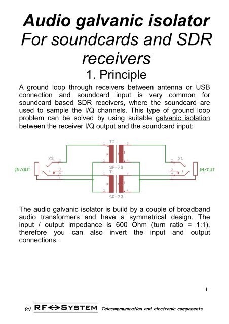
Um, if you want to be 100% safe, you can make an extra audio cable/interface with galvanic insulation. That way, no ground loop etc between the Covox device and active speaker box/hifi stereo can happen.

If the Covox is mono, a simple 1:1 audio transformer (AF transfomer) will do. Or a capacitor in series (about 1 uF).
If the Covox is stereo, you need two of them for L/R channel, respectively.

Anyway, these are just ideas. The Covox circuit may already have a decoupling capacitor near the 3,5mm jack.

It just came to mind, because I often use galvanic insulation for my radio hobby (shortwave radio <-> soundcard).
It's possible that such little galvanic insulator boxes already exist commercially.

If not, here's a schematic.

audio-galvanic-isolator-for-soundcards-and-sdr-receivers-rf-system.jpg
PDF: http://www.rfsystem.it/shop/download/Audio_isolator.pdf

Another one. If you like, add a ~100 Ohm resistor on the source side (Covox side) in series, if you're worried of shorting something.
It's usually not needed, though. The coil as such is fine, normally, it has an resistance+impedance of its own.
The "loop" or ring shown is merely a symbol for the shielding of the audio cable, it's not a connection.

The attachment 1rxtransformer.GIF is no longer available

Source: https://www.soundcardpacket.org/7cablerx.aspx

Generally speaking, the impedance (high vs low) is merely important on the output side, the transmitter. So it's not mismatched. The input side, the receiver, is more forgiving.
(^seen from perspective of the devices rather than the cable.)

Again, generally speaking. In low-power audio applications, messing things up doesn't really harm anything. It's just inefficient, causes distortion etc.

In the past, I've been using old AC transformers from broken radios and big old power bricks.
The lower voltage side is low impedance (a few dozen to few hundred ohms; closer to headphones levels),
the high voltage side is high-impedance (in the kohms/closer to a soundcard's line-in level).

If the Covox is meant for headphones use (about 16 to to 64 Ohms, as typical for walkman headphones), it's rather low impedance.

Anyway, these are just my two cents. Normally, you can omit all of this.
It just came to mind, because of my radio hobby. There, you want to avoid the RF noise going back and forth between PC and radio.

In normal cases, it's not needed. Ferrites on the cables can also help to reduce sheath current, though.
That's what often causes all kinds of trouble these days. As a workaround, ferrite clips can be attached to power chords of switching PSUs. Those thick rings around VGA cables and some USB cables are ferrite rings, too.

"Time, it seems, doesn't flow. For some it's fast, for some it's slow.
In what to one race is no time at all, another race can rise and fall..." - The Minstrel

//My video channel//

Reply 4 of 4, by Ensign Nemo

User metadata
Rank Oldbie
Rank
Oldbie

Thanks again!

It seems like I should be okay with the wood enclosure, as I'm not looking to go overboard or anything like that. This is replaceable if I end up being unlucky. I just wanted to make sure that I'm not doing anything that is a bad idea.

I actually picked up a USB cable with a ferrite choke and a cheap ground loop isolator because I was having terrible noise and hum with this device. It was so bad that it wasn't useable. I'm not sure if the ground loop isolator is similar to the galvanic isolator you described, but it certainly worked for cleaning up the noise.